
Loose Leaf for Engineering Circuit Analysis Format: Loose-leaf
9th Edition
ISBN: 9781259989452
Author: Hayt
Publisher: Mcgraw Hill Publishers
expand_more
expand_more
format_list_bulleted
Videos
Textbook Question
Chapter 15, Problem 71E
The network of Fig. 15.72 was implemented as a low-pass filter designed with a corner frequency of 1250 rad/s. Its performance is inadequate in two respects: (1) a voltage gain of at least 2 dB is required, and (2) the magnitude of the output voltage does not decrease quickly enough in the stopband. Design a better alternative if only one op amp is available and only two 1 μF capacitors can be located.
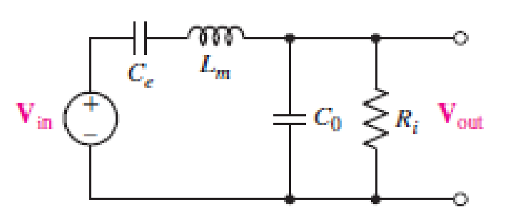
FIGURE 15.72
Expert Solution & Answer
Want to see the full answer?
Check out a sample textbook solution
Students have asked these similar questions
The cascaded RF filters of a TRF receiver have 590µH inductors. The variable capacitors have a capacitance tuning ratio of 6.5. With these filters, the receiver can tune to a minimum of 500kHz.a. determine the maximum capacitance of the variable capacitors b. determine the minimum capacitance of the variable capacitors c. what is the maximum resonant frequency of the RF filters?
1. A series RLC circuit has a Q of 75 and a pass band between half-power frequencies of 160 cps. Calculate the frequency of resonance and upper and lower frequencies of the pass band.
2. A 15.9 uF capacitor and a 15.1 mH inductor are connected in parallel. In series with these units are a variable resistor R and an adjustable device X, joined in series. (a) Determine the kind and size of device X (inductance in Henry or capacitance in Farad) when the circuit is connected to a 50 volt 400 cps source and is adjusted to resonance. (b) For the resonant condition, calculate the value of R if the voltage drop across the paralleled units is to be 100 volts.
3. An impedance coil having a resistance of 30 ohms and a 50 cps inductive reactance of 33.3 ohms is connected to a 125 volt 60 cps source. A series circuit consisting of a 20 ohm resistor and a variable capacitor is then connected in parallel with the coil. (a) for what values of capacitance will the circuit be in resonance? (b)…
DESIGNPROBLEM_PSPICEMULTISIM Use a 500 nF capacitor to design a bandreject filter, as shown . The filter has a center frequency of 4 kHz and a quality factor of 5.
1. a) Specify the numerical values of R and L. 2. b) Calculate the upper and lower corner, or cutoff, frequencies in kilohertz. 3. c) Calculate the filter bandwidth in kilohertz.
Chapter 15 Solutions
Loose Leaf for Engineering Circuit Analysis Format: Loose-leaf
Ch. 15.1 - Write an expression for the transfer function of...Ch. 15.2 - Calculate HdB at = 146 rad/s if H(s) equals (a)...Ch. 15.2 - Prob. 3PCh. 15.2 - Draw the Bode phase plot for the transfer function...Ch. 15.2 - Construct a Bode magnitude plot for H(s) equal to...Ch. 15.2 - Draw the Bode phase plot for H(s) equal to (a)...Ch. 15.2 - Prob. 7PCh. 15.3 - A parallel resonant circuit is composed of the...Ch. 15.3 - Prob. 9PCh. 15.4 - A marginally high-Q parallel resonant circuit has...
Ch. 15.5 - A series resonant circuit has a bandwidth of 100...Ch. 15.6 - Referring to the circuit of Fig. 15.25a, let R1 =...Ch. 15.6 - Prob. 13PCh. 15.6 - Prob. 14PCh. 15.6 - The series combination of 10 and 10 nF is in...Ch. 15.7 - A parallel resonant circuit is defined by C = 0.01...Ch. 15.8 - Design a high-pass filter with a cutoff frequency...Ch. 15.8 - Design a bandpass filter with a low-frequency...Ch. 15.8 - Design a low-pass filter circuit with a gain of 30...Ch. 15 - For the RL circuit in Fig. 15.52, (a) determine...Ch. 15 - For the RL circuit in Fig. 15.52, switch the...Ch. 15 - Examine the series RLC circuit in Fig. 15.53, with...Ch. 15 - For the circuit in Fig. 15.54, (a) derive an...Ch. 15 - For the circuit in Fig. 15.55, (a) derive an...Ch. 15 - For the circuit in Fig. 15.56, (a) determine the...Ch. 15 - For the circuit in Fig. 15.57, (a) determine the...Ch. 15 - Sketch the Bode magnitude and phase plots for the...Ch. 15 - Use the Bode approach to sketch the magnitude of...Ch. 15 - If a particular network is described by transfer...Ch. 15 - Use MATLAB to plot the magnitude and phase Bode...Ch. 15 - Determine the Bode magnitude plot for the...Ch. 15 - Determine the Bode magnitude and phase plot for...Ch. 15 - Prob. 15ECh. 15 - Prob. 16ECh. 15 - For the circuit of Fig. 15.56, construct a...Ch. 15 - Construct a magnitude and phase Bode plot for the...Ch. 15 - For the circuit in Fig. 15.54, use LTspice to...Ch. 15 - For the circuit in Fig. 15.55, use LTspice to...Ch. 15 - Prob. 21ECh. 15 - A certain parallel RLC circuit is built using...Ch. 15 - A parallel RLC network is constructed using R = 5...Ch. 15 - Prob. 24ECh. 15 - Delete the 2 resistor in the network of Fig....Ch. 15 - Delete the 1 resistor in the network of Fig....Ch. 15 - Prob. 28ECh. 15 - Prob. 29ECh. 15 - Prob. 30ECh. 15 - A parallel RLC network is constructed with a 200 H...Ch. 15 - Prob. 32ECh. 15 - A parallel RLC circuit is constructed such that it...Ch. 15 - Prob. 34ECh. 15 - Prob. 35ECh. 15 - An RLC circuit is constructed using R = 5 , L = 20...Ch. 15 - Prob. 37ECh. 15 - Prob. 38ECh. 15 - For the network of Fig. 15.25a, R1 = 100 , R2 =...Ch. 15 - Assuming an operating frequency of 200 rad/s, find...Ch. 15 - Prob. 41ECh. 15 - Prob. 42ECh. 15 - For the circuit shown in Fig. 15.64, the voltage...Ch. 15 - Prob. 44ECh. 15 - Prob. 45ECh. 15 - Prob. 46ECh. 15 - The filter shown in Fig. 15.66a has the response...Ch. 15 - Prob. 48ECh. 15 - Examine the filter for the circuit in Fig. 15.68....Ch. 15 - Examine the filter for the circuit in Fig. 15.69....Ch. 15 - (a)Design a high-pass filter with a corner...Ch. 15 - (a) Design a low-pass filter with a break...Ch. 15 - Prob. 53ECh. 15 - Prob. 54ECh. 15 - Design a low-pass filter characterized by a...Ch. 15 - Prob. 56ECh. 15 - The circuit in Fig. 15.70 is known as a notch...Ch. 15 - (a) Design a two-stage op amp filter circuit with...Ch. 15 - Design a circuit which removes the entire audio...Ch. 15 - Prob. 61ECh. 15 - If a high-pass filter is required having gain of 6...Ch. 15 - (a) Design a second-order high-pass Butterworth...Ch. 15 - Design a fourth-order high-pass Butterworth filter...Ch. 15 - (a) Design a Sallen-Key low-pass filter with a...Ch. 15 - (a) Design a Sallen-Key low-pass filter with a...Ch. 15 - A piezoelectric sensor has an equivalent circuit...Ch. 15 - Design a parallel resonant circuit for an AM radio...Ch. 15 - The network of Fig. 15.72 was implemented as a...Ch. 15 - Determine the effect of component tolerance on the...
Additional Engineering Textbook Solutions
Find more solutions based on key concepts
Write the nodal equations for the network of Fig. 8.137 using the general approach. Find the nodal voltages usi...
Introductory Circuit Analysis (13th Edition)
Explain the main function of each of the following major components of a PLC: a. Processor module (CPU) b. I/O ...
Programmable Logic Controllers
Assume a telephone signal travels through a cable at two-thirds the speed of light. How long does it take the s...
Electric Circuits (10th Edition)
A constant voltage of 10V is applied to a 50H inductance, as shown in Figure P3.51 Figure P3 51 The current in ...
Electrical Engineering: Principles & Applications (7th Edition)
The voltage source of the circuit shown in Fig. P1.29 is given by s(t)=25cos(4104t45)(V). Obtain an expression ...
Fundamentals of Applied Electromagnetics (7th Edition)
When travelers from the USA and Canada visit Europe, they encounter a different power distribution system. Wall...
Electric machinery fundamentals
Knowledge Booster


Learn more about
Need a deep-dive on the concept behind this application? Look no further. Learn more about this topic, electrical-engineering and related others by exploring similar questions and additional content below.Similar questions
- Design a bandpass filter for a graphic equalizer to provide an amplification of2 within the band of frequencies between 100 and 10,000 Hz. Use 0.2 μFcapacitors.arrow_forwardFind the gain of the following circuit and the lower and upper cutoff frequencies. (RS = 1 kΩ, R1 = 40 kΩ, R2 = 10kΩ, RC = 20 kΩ, RE = 30 kΩ, RL = 2.2 kΩ, CS = 10 µF, CC = 1 µF, CE = 20 µF, Cbe = 20 pF, Cbc = 30 pF,VT = 26mV, β = 100, ro = infinityarrow_forwardRC=10 kΩ, RE=5 kΩ, RL=2.2 kΩ, CS=10 µF, CC=1 µF, CE=20 µF, Cbe=20 pF, Cbc=10 pF,VT=26mV, β=100, ro=sonsuz vcc=20 RS=1 kΩ, R1=40 kΩ, R2=10 Find the gain of the circuit below and the lower and upper cutoff frequencies.arrow_forward
- y[z]=6cos2(pi×z/4)a.The above equation shows a discrete time signal, y[z] from a device, determine the four point DFT of the sequence.H(ejw) = {1, 0≤|w|≤wC {0, WC |W|< π b.The expression above shows the DTFT of a lowpass filter system. In order to get the impulse response h[n], determine the inverse DTFT of the systemarrow_forwardA measurement to be used to measure the voltage numerically in electrical energy systemssystem, according to time expressionv= 311sin (314t) + 50sin (1570t + 20o) + 40sin (3454t + 30o) (V)A voltage sign is applied. The analog filter in this measuring systemIt is meant to pass the last component in the voltage expression, destroying the first and second component. First order RC filter will be designed for the above measurement system. Draw the circuit of the filter. Infer the transfer function.arrow_forwardH5. A channel has the following (sampled) impulse response: h = [−0.15, 0.70, 0.35, 0.20]. Calculate a ZF equalizer with 5 coefficients that can compensate for this channel. Would it be advantageous to use an equalizer with more coefficients?arrow_forward
- 6) An angle-modulated signal has the form s(t) = 100 cos (2π fc t + 3 sin (2πfm t)) Where fc= 5 MHz and fm = 500 Hz. Assuming that it is an FM signal, determine and index of modulation and the bandwidth of the signal.arrow_forward1. The resistance and inductance of the circuit are 100Ω and 20mH, respectively.1. Find the value of C that makes the voltage response criticallydamped.2. If C is adjusted to give a neper frequency of 5krad/s, find the valueof C and the roots of the characteristic equation.3. If C is adjusted to give a resonant frequency of 20krad/s, find thevalue of C and the roots of the characteristic equation.arrow_forwardA summary of the results is as follows: Frequency = 1.01 kHz: Input = 1.51 V; Output = 1.44 V Frequency = 10.06 kHz: Input = 1.37 V; Output = 0.62 V Frequency = 102.8 kHz: Input = 1.31 V; Output = 90 mV The resistor was measured to be 331.4 Ω and the capacitor to be 96.3 nF. (1) Calculate values of the transfer function, using the formula above, at the frequencies that were investigated and compare them to the ratios of the measured output and input voltages at each frequency. A summary of the results is as follows: Frequency = 1.01 kHz: Input = 1.50 V; Output = 1.44 V Frequency = 10.06 kHz: Input = 1.20 V; Output = 0.50 V Frequency = 102.8 kHz: Input = 1.13 V; Output = 70 mV The resistor was measured to be 150.1 Ω and the capacitor to be 233.6 nF. (2) Are the ratios of the output voltage to input voltage for this filter similar to the ratios of the first low-pass filter? Does it make sense based on the transfer function how the ratios compare?arrow_forward
- DESIGNPROBLEM_Using a 100 nF capacitor, design a highpass passive filter with a cutoff frequency of 300 Hz. 1. a) Specify the value of R in kilohms. 2. b) A 47 kΩ resistor is connected across the output terminals of the filter. What is the cutoff frequency, in hertz, of the loaded filter?arrow_forwardDetermine and sketch the magnitude response and system response of the following LCCDE system : .arrow_forwardMeasurements conducted on a servomechanism show the system response to be: C (t) = 0.3 e 60t + 1.5 e 10t, when subjected to a unit step input. [1].Obtain the expression for the closed-loop transfer function. [2].Determine the undamped natural frequency and damping ratio of the system.arrow_forward
arrow_back_ios
SEE MORE QUESTIONS
arrow_forward_ios
Recommended textbooks for you
 Introductory Circuit Analysis (13th Edition)Electrical EngineeringISBN:9780133923605Author:Robert L. BoylestadPublisher:PEARSON
 Delmar's Standard Textbook Of ElectricityElectrical EngineeringISBN:9781337900348Author:Stephen L. HermanPublisher:Cengage Learning
 Programmable Logic ControllersElectrical EngineeringISBN:9780073373843Author:Frank D. PetruzellaPublisher:McGraw-Hill Education
 Fundamentals of Electric CircuitsElectrical EngineeringISBN:9780078028229Author:Charles K Alexander, Matthew SadikuPublisher:McGraw-Hill Education
 Electric Circuits. (11th Edition)Electrical EngineeringISBN:9780134746968Author:James W. Nilsson, Susan RiedelPublisher:PEARSON
 Engineering ElectromagneticsElectrical EngineeringISBN:9780078028151Author:Hayt, William H. (william Hart), Jr, BUCK, John A.Publisher:Mcgraw-hill Education,
Introductory Circuit Analysis (13th Edition)
Electrical Engineering
ISBN:9780133923605
Author:Robert L. Boylestad
Publisher:PEARSON
Delmar's Standard Textbook Of Electricity
Electrical Engineering
ISBN:9781337900348
Author:Stephen L. Herman
Publisher:Cengage Learning
Programmable Logic Controllers
Electrical Engineering
ISBN:9780073373843
Author:Frank D. Petruzella
Publisher:McGraw-Hill Education
Fundamentals of Electric Circuits
Electrical Engineering
ISBN:9780078028229
Author:Charles K Alexander, Matthew Sadiku
Publisher:McGraw-Hill Education
Electric Circuits. (11th Edition)
Electrical Engineering
ISBN:9780134746968
Author:James W. Nilsson, Susan Riedel
Publisher:PEARSON
Engineering Electromagnetics
Electrical Engineering
ISBN:9780078028151
Author:Hayt, William H. (william Hart), Jr, BUCK, John A.
Publisher:Mcgraw-hill Education,
Systems and Simulation - Lecture 3: Modelling of Mechanical systems; Author: bioMechatronics Lab;https://www.youtube.com/watch?v=fMcDdyoC9mA;License: Standard Youtube License