
Videos
A load P is supported as shown by a steel pin that has been inserted in a short wooden member hanging from the ceiling. The ultimate strength of the wood used is 60 MPa in tension and 7.5 MPa in shear, while the ultimate strength of the steel is 145 MPa in shear. Knowing that b = 40 mm, c = 55 mm, and d = 12 mm, determine the load P if an overall factor of safety of 3.2 is desired.
Fig. P1.47
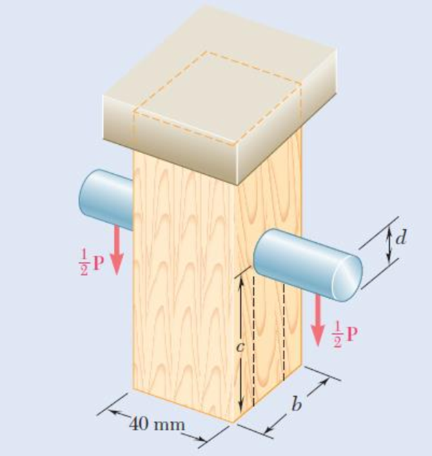
1.48 For the support of Prob. 1.47, knowing that the diameter of the pin is d = 16 mm and that the magnitude of the load is P = 20 kN, determine (a) the factor of safety for the pin (b) the required values of b and c if the factor of safety for the wooden member is the same as that found in part a for the pin.
Want to see the full answer?
Check out a sample textbook solution
Chapter 1 Solutions
Package: Loose Leaf For Mechanics Of Materials With 1 Semester Connect Access Card


- In the steel structure shown, a 6-mm-diameter pin is used at C and 12-mm-diameter pins are used at B and D. The ultimate shearing stress is 150 MPa at all connections, and the ultimate normal stress is 350 MPa in link BD. Knowing that a factor of safety of 3.0 is desired, determine the largest load P that can be applied at A. Note that link BD is not reinforced around the pin holes. The largest load P that can be applied at A is kN.arrow_forwardEach of the two vertical links CF connecting the two horizontal members AD and EG has a 10x40-mm uniform rectangular cross section and is made of a steel with an ultimate strength in tension of 400 MPa,while each of the pins at C and F has a 20-mm diameter and is made of a steel with an ultimate strength in shear of 150 MPa. Determine the overall factor of safety for the links CF and the pins connecting them to the horizontal members.arrow_forwardA steel loop ABCD of length 5 ft and of 3838 -in. diameter is placed as shown around a 1-in.-diameter aluminum rod AC. Cables BE and DF, each of 1212 -in. diameter, are used to apply the load Q. Knowing that the ultimate strength of the steel used for the loop and the cables is 75 ksi, and that the ultimate strength of the aluminum used for the rod is 45 ksi, determine the largest load Q that can be applied if an overall factor of safety of 3 is desired. The largest load Q that can be applied is kips.arrow_forward
- (a) Considering only buckling in the plane of the structure shown and using Euler’s formula, determine the value of θbetween 0 and 90° for which the allowable magnitude of the load P is maximum. (b) Determine the corresponding maximum value of P knowing that a factor of safety of 3.2 is required. Use E= 29 x 106 psi.arrow_forwardColumn ABC has a uniform rectangular cross section and is braced in the xz plane at its midpoint C. (a) Determine the ratio b/d for which the factor of safety is the same with respect to buckling in the xz and yz planes. (b) Using the ratio found in part a, design the cross section of the column so that the factor of safety will be 3.0 when P= 4.4 kN, L=1 m, and E=200 GPaarrow_forwardTHe bracket shown is made of cold drawn steel with Sy=400MPa and Su=480 MPa, and is fastened to a beam made of the same material by five rivets that are made of a steel with Sy=300 MPa and Sut=365 MPa. The thickness of the bracket and the beam are 12 mm and 16 mm respectively.Diameters of the rivets are 20 mm. What safe load F(steady) can be supported by the riveted joint for a factor of safety of 2. Use distortion energy theory of failure.arrow_forward
- A14-kN tensile load will be applied to a 50-m length of steel wire with E = 200 GPa. Determine the smallest diameter wire that can be used, knowing that the normal stress must not exceed 150 MPa and that the increase in length of the wire must not exceed 25 mm. The smallest diameter that can be used is ___mm?arrow_forwardIn the steel structure shown, a 6-mm-diameter pin is used at C and10-mm-diameter pins are used at B and D. The ultimate shearing stress is 150 MPa at all connections, and the ultimate normal stress is 400 MPa in link BD. Knowing that a factor of safety of 3.0 is desired,determine the largest load P that can be applied at A. Note that link BD is not reinforced around the pin holes.arrow_forwardIn the structure shown, an 8-mm diameter pin is used at A, and 12- mm diameter pins are used at B and D. Knowing that the ultimate shearing stresses is 100 MPa at all connections and that the ultimate normal stress is 250 MPa in each of the two links joining B and D, determine the allowable load P if an overall factor of safety of 3.0 is desired.arrow_forward
- Two cylindrical rods, one of steel and the other of brass, are joined at C and restrained by rigid supports at A and E. The steel rod has a length of 300 mm while the brass rod has a length of 200 mm. The diameters of the rods are shown in the figure below. A force of 60 kN is applied at point B of the steel segment. For the loading shown and knowing that modulus of elasticity values for steel and brass are respectively Es = 200 GPa and Eb = 105 GPa, determine a.) The reactions at A and E: RA and RE. b.) The deflection of point C from its original location. how to doarrow_forwardMember ABC, which is supported by a pin and bracket at C and a cable BD, was designed to support the 20-kN load P as shown. The pin at C has 20 mm diameter. a) Draw complete free body diagram of member ABC and determine all forces acting upon it b) If pin at C was made from steel with ultimate shear stress 300 MPa, calculate its factor of safety c) Knowing that rope BD made of a material has allowable stress of 50 MPa, calculate its diameter d) Use the information in part c, find the Young’s modulus of the rope material knowing that its length is 0.5 m and stretched by 0.5 mm upon the shown loading.arrow_forwardIn the structure shown, an 8-mm-diameter pin is used at A and 12 mmdiameter pins are used at B and D. Knowing that the ultimate shearingstress is 100 MPa at all connections and the ultimate normal stress is 250 MPa in each of the two links joining B and D, determine the allowable load P if an overall factor of safety of 3.0 is desired.arrow_forward
 Elements Of ElectromagneticsMechanical EngineeringISBN:9780190698614Author:Sadiku, Matthew N. O.Publisher:Oxford University Press
 Mechanics of Materials (10th Edition)Mechanical EngineeringISBN:9780134319650Author:Russell C. HibbelerPublisher:PEARSON
 Thermodynamics: An Engineering ApproachMechanical EngineeringISBN:9781259822674Author:Yunus A. Cengel Dr., Michael A. BolesPublisher:McGraw-Hill Education
 Control Systems EngineeringMechanical EngineeringISBN:9781118170519Author:Norman S. NisePublisher:WILEY
 Mechanics of Materials (MindTap Course List)Mechanical EngineeringISBN:9781337093347Author:Barry J. Goodno, James M. GerePublisher:Cengage Learning
 Engineering Mechanics: StaticsMechanical EngineeringISBN:9781118807330Author:James L. Meriam, L. G. Kraige, J. N. BoltonPublisher:WILEY