Package: Loose Leaf For Mechanics Of Materials With 1 Semester Connect Access Card
7th Edition
ISBN: 9781259290527
Author: BEER
Publisher: MCG
expand_more
expand_more
format_list_bulleted
Videos
Textbook Question
Chapter 1.5, Problem 31P
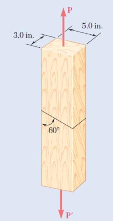
The 1.4-kip load P is supported by two wooden members of uniform cross section that are joined by the simple glued scarf splice shown. Determine the normal and shearing stresses in the glued splice.
Fig. P1.31 and P1.32
Expert Solution & Answer
Want to see the full answer?
Check out a sample textbook solution
Students have asked these similar questions
Two gage marks are placed exactly 250 mm apart on a 12-mm-diameter aluminum rod with E = 73 GPa and an ultimate strength of 140 MPa. Knowing that the distance between the gage marks is 250.28 mm after a load is applied, determine the stress in the rod
For the truss and loading shown, determine the magnitude of the normal stress(in psi) in member CE, knowing that the cross-sectional area of that member is 3.67 in2 if P = 30505 lb, Q = 34758 lb, and y = 7.35 ft. Round off the final answer to two decimal places.
Two forces P can be applied separately or at the same time to a plate that is welded to a solid circular bar of radius r. Determine the largest compressive stress in the circular bar (a) when both forces are applied, (b) when only one of the forces is applied.
Chapter 1 Solutions
Package: Loose Leaf For Mechanics Of Materials With 1 Semester Connect Access Card
Ch. 1.2 - Two solid cylindrical rods AB and BC are welded...Ch. 1.2 - Two solid cylindrical rods AB and BC are welded...Ch. 1.2 - Two solid cylindrical rods AB and BC are welded...Ch. 1.2 - Two solid cylindrical rods AB and BC are welded...Ch. 1.2 - A strain gage located at C on the surface of bone...Ch. 1.2 - Two brass rods AB and BC, each of uniform...Ch. 1.2 - Each of the four vertical links has an 8 36-mm...Ch. 1.2 - Link AC has a uniform rectangular cross section 18...Ch. 1.2 - Three forces, each of magnitude P = 4 kN, are...Ch. 1.2 - Link BD consists of a single bar 1 in. wide and 12...
Ch. 1.2 - For the Pratt bridge truss and loading shown,...Ch. 1.2 - The frame shown consists of four wooden members,...Ch. 1.2 - An aircraft tow bar is positioned by means of a...Ch. 1.2 - Two hydraulic cylinders are used to control the...Ch. 1.2 - Determine the diameter of the largest circular...Ch. 1.2 - Two wooden planks, each 12 in. thick and 9 in....Ch. 1.2 - When the force P reached 1600 lb, the wooden...Ch. 1.2 - A load P is applied to a steel rod supported as...Ch. 1.2 - The axial force in the column supporting the...Ch. 1.2 - Three wooden planks are fastened together by a...Ch. 1.2 - A 40-kN axial load is applied to a short wooden...Ch. 1.2 - An axial load P is supported by a short W8 40...Ch. 1.2 - Link AB, of width b = 2 in. and thickness t=14...Ch. 1.2 - Determine the largest load P that can be applied...Ch. 1.2 - Knowing that = 40 and P = 9 kN, determine (a) the...Ch. 1.2 - The hydraulic cylinder CF, which partially...Ch. 1.2 - For the assembly and loading of Prob. 1.7,...Ch. 1.2 - Two identical linkage-and-hydraulic-cylinder...Ch. 1.5 - Two wooden members of uniform rectangular cross...Ch. 1.5 - Two wooden members of uniform rectangular cross...Ch. 1.5 - The 1.4-kip load P is supported by two wooden...Ch. 1.5 - Two wooden members of uniform cross section are...Ch. 1.5 - A centric load P is applied to the granite block...Ch. 1.5 - A 240-kip load P is applied to the granite block...Ch. 1.5 - A steel pipe of 400-mm outer diameter is...Ch. 1.5 - A steel pipe of 400-mm outer diameter is...Ch. 1.5 - A steel loop ABCD of length 5 ft and of 38-in....Ch. 1.5 - Link BC is 6 mm thick, has a width w = 25 mm, and...Ch. 1.5 - Link BC is 6 mm thick and is made of a steel with...Ch. 1.5 - Members AB and BC of the truss shown are made of...Ch. 1.5 - Members AB and BC of the truss shown are made of...Ch. 1.5 - Link AB is to be made of a steel for which the...Ch. 1.5 - Two wooden members are joined by plywood splice...Ch. 1.5 - For the joint and loading of Prob. 1.43, determine...Ch. 1.5 - Three 34-in.-diameter steel bolts are to be used...Ch. 1.5 - Three steel bolts are to be used to attach the...Ch. 1.5 - A load P is supported as shown by a steel pin that...Ch. 1.5 - A load P is supported as shown by a steel pin that...Ch. 1.5 - A steel plate 14 in. thick is embedded in a...Ch. 1.5 - Determine the factor of safety for the cable...Ch. 1.5 - Link AC is made of a steel with a 65-ksi ultimate...Ch. 1.5 - Solve Prob. 1.51, assuming that the structure has...Ch. 1.5 - Each of the two vertical links CF connecting the...Ch. 1.5 - Solve Prob. 1.53, assuming that the pins at C and...Ch. 1.5 - In the structure shown, an 8-mm-diameter pin is...Ch. 1.5 - In an alternative design for the structure of...Ch. 1.5 - Prob. 57PCh. 1.5 - The Load and Resistance Factor Design method is to...Ch. 1 - In the marine crane shown, link CD is known to...Ch. 1 - Two horizontal 5-kip forces are applied to pin B...Ch. 1 - For the assembly and loading of Prob. 1.60,...Ch. 1 - Two steel plates are to be held together by means...Ch. 1 - A couple M of magnitude 1500 N m is applied to...Ch. 1 - Knowing that link DE is 18 in. thick and 1 in....Ch. 1 - A 58-in.-diameter steel rod AB is fitted to a...Ch. 1 - In the steel structure shown, a 6-mm-diameter pin...Ch. 1 - Prob. 67RPCh. 1 - A force P is applied as shown to a steel...Ch. 1 - The two portions of member AB are glued together...Ch. 1 - The two portions of member AB are glued together...
Knowledge Booster


Learn more about
Need a deep-dive on the concept behind this application? Look no further. Learn more about this topic, mechanical-engineering and related others by exploring similar questions and additional content below.Similar questions
- 6. A strain gage located at C on the surface of bone AB indicates that the average normal stress in the bone is 3.80 MPa when the bone is subjected to two 1200-N forces as shown. Assuming the cross section of the bone at C to be annular and knowing that its outer diameter is 25 mm, determine the inner diameter of the bone’s cross section at C.arrow_forwardA 50-kN force is subjected to a lap joint fastened by three 20-mm diameter rivets.(a) the shearing stress in each rivet.(b) the bearing stress in each plate.(c) the maximum average tensile stress in each plate. Assume that the axial load P is distributed equally amongthe three rivets. equally among the three rivets.arrow_forwardThree rods of different materials are connected and placed between rigid supports at A and D, as shown below. Properties for each of the three rods are given below. The bars are initially unstressed when the structure is assembled at 70°F. After the temperature has been increased to 250°F, determine: (a) the normal stresses in the three rods. (b) the force exerted on the rigid supports. (c) the deflections of joints B and C relative to rigid support A.arrow_forward
- Two gage marks are placed exactly 250 mm apart on a 12-mm-diameter aluminum rod with E5 73 GPa and an ultimate strength of 140 MPa. Knowing that the distance between the gage marks is 250.28 mm after a load is applied, determine (a) the stress in the rod, (b) the factor of safety.arrow_forwardThe lap joint shown is connected by 6 pieces rivets. Assuming that the load P = 70 KN is carried equally by the six rivets.Determine the diameter of the rivets if the allowable shear stress is 148.54 MPa.arrow_forwardThe Bars of the Pin-connected frame as shown are each 30mm and 60mm in section. Determine the maximum load P that can be applied without exceeding the allowable stresses of 100 MN/m2 in tension and 80 MN/m2 in compression.arrow_forward
- A 5-kN tensile load will be applied to a 50-m length of steel wire with E = 200 GPa. Determine the smallest diameter wire that can be used, knowing that the normal stress must not exceed 150 MPa and that the increase in length of the wire must not exceed 25 mm.arrow_forwardThe lap joint shown is connected by three 16-mm diameter rivets. If the allowable stress for shear in rivets is 40 MPa and bearing between therivets and the plates is 60 MPa determine the safe load P.arrow_forwardA compressive member of a structure is of 25 mm square cross-section and carries a load of 50 kN. Determine, from first principles, the normal, tangential, and resultant stresses on a plane inclined at 60° to the axis of the bar.arrow_forward
- Two wooden planks, each 1212 in. thick and 9 in. wide, are joined by the dry mortise joint shown. Knowing that the wood used shears off along its grain when the average shearing stress reaches 1.8 ksi, determine the magnitude P of the axial load that will cause the joint to fail. The magnitude P of the axial load that will cause the joint to fail is kips.arrow_forwardTwo wooden members of uniform cross section are joined by the simple scarf splice shown. Knowing that the maximum allowable tensile stress in the glued splice is 90 psi, determine the largest load P that can be safely supported if W = 2.4 in, L = 8.2 in and θ= 51.8. Round off the final answer to two decimal places.arrow_forwardThree wooden planks are fastened together by a series of bolts to form a column. The diameter of each bolt is 12 mm and the inner diameter of each washer is 16 mm, which is slightly larger than the diameter of the holes in the planks. Determine the smallest allowable outer diameter d of the washers, knowing that the average normal stress in the bolts is 36 MPa and that the bearing stress between the washers and the planks must not exceed 8.5 MPa.arrow_forward
arrow_back_ios
SEE MORE QUESTIONS
arrow_forward_ios
Recommended textbooks for you
 Elements Of ElectromagneticsMechanical EngineeringISBN:9780190698614Author:Sadiku, Matthew N. O.Publisher:Oxford University Press
 Mechanics of Materials (10th Edition)Mechanical EngineeringISBN:9780134319650Author:Russell C. HibbelerPublisher:PEARSON
 Thermodynamics: An Engineering ApproachMechanical EngineeringISBN:9781259822674Author:Yunus A. Cengel Dr., Michael A. BolesPublisher:McGraw-Hill Education
 Control Systems EngineeringMechanical EngineeringISBN:9781118170519Author:Norman S. NisePublisher:WILEY
 Mechanics of Materials (MindTap Course List)Mechanical EngineeringISBN:9781337093347Author:Barry J. Goodno, James M. GerePublisher:Cengage Learning
 Engineering Mechanics: StaticsMechanical EngineeringISBN:9781118807330Author:James L. Meriam, L. G. Kraige, J. N. BoltonPublisher:WILEY
Elements Of Electromagnetics
Mechanical Engineering
ISBN:9780190698614
Author:Sadiku, Matthew N. O.
Publisher:Oxford University Press
Mechanics of Materials (10th Edition)
Mechanical Engineering
ISBN:9780134319650
Author:Russell C. Hibbeler
Publisher:PEARSON
Thermodynamics: An Engineering Approach
Mechanical Engineering
ISBN:9781259822674
Author:Yunus A. Cengel Dr., Michael A. Boles
Publisher:McGraw-Hill Education
Control Systems Engineering
Mechanical Engineering
ISBN:9781118170519
Author:Norman S. Nise
Publisher:WILEY
Mechanics of Materials (MindTap Course List)
Mechanical Engineering
ISBN:9781337093347
Author:Barry J. Goodno, James M. Gere
Publisher:Cengage Learning
Engineering Mechanics: Statics
Mechanical Engineering
ISBN:9781118807330
Author:James L. Meriam, L. G. Kraige, J. N. Bolton
Publisher:WILEY
An Introduction to Stress and Strain; Author: The Efficient Engineer;https://www.youtube.com/watch?v=aQf6Q8t1FQE;License: Standard YouTube License, CC-BY