Connect 2 Semester Access Card for Vector Mechanics for Engineers: Statics and Dynamics
11th Edition
ISBN: 9780077687298
Author: Ferdinand P. Beer, E. Russell Johnston Jr., David Mazurek, Phillip J. Cornwell
Publisher: McGraw-Hill Education
bartleby

Concept explainers

bartleby

Videos

Question
Book Icon
Chapter 15.1, Problem 15.23P

(a)

To determine

The angular velocity and angular acceleration of the point C on the output belt.

(a)

Expert Solution
Check Mark

Answer to Problem 15.23P

The angular velocity (vC) and angular acceleration (αC) of the point C on the output belt is 0.5ft/s()_ and 1.50ft/s2()_ respectively.

Explanation of Solution

Given information:

The inner radius of left pulley (r1) is 2 in..

The outer radius of left pulley (r2) is 4 in..

The velocity of point A (vA) to the right is 2 ft/s.

The tangential component of acceleration of point A (aA)t is 6ft/s2.

The inner radius of right pulley (r3) is 2 in..

The outer radius of right pulley (r4) is 4 in..

Calculation:

Left pulley:

Determine the angular velocity of the left pulley ω1 using the relation.

ω1=vAr2

Substitute 2 ft/s for vA and 4 in. for r2.

ω1=24in.×1ft12in.=6rad/s(Clockwise)

Draw the free body diagram of the left pulley as in Figure (1).

Connect 2 Semester Access Card for Vector Mechanics for Engineers: Statics and Dynamics, Chapter 15.1, Problem 15.23P , additional homework tip  1

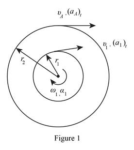
Determine the angular acceleration of the left pulley α1 using the relation.

α1=(aA)tr2

Substitute 6ft/s2 for (aA)t and 4 in. for r2.

α1=64in.×1ft12in.=18rad/s2=18rad/s2(Anticlockwise)

Intermediate belt:

Determine the velocity of the intermediate belt v1 using the relation.

v1=r1ω1

Substitute 2 in. for r1 and 6rad/s for ω1.

v1=2in.×1ft12in.×6=1ft/s

Determine the tangential component of acceleration of the intermediate belt (a1)t using the relation.

(a1)t=r1α1

Substitute 2 in. for r1 and 18rad/s2 for α1.

(a1)t=2in.×1ft12in.×18=3ft/s2

Right pulley:

Draw the free body diagram of the right pulley as in Figure (2).

Connect 2 Semester Access Card for Vector Mechanics for Engineers: Statics and Dynamics, Chapter 15.1, Problem 15.23P , additional homework tip  2

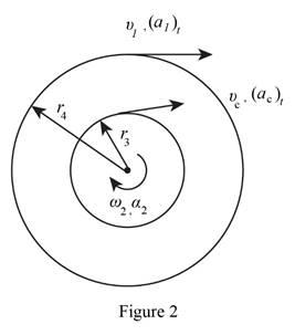
Determine the angular velocity of the right pulley ω2 using the relation.

ω2=v1r4

Substitute 1 ft/s for v1 and 4 in. for r4.

ω2=14in.×1ft12in.=3rad/s(Clockwise)

Determine the angular acceleration of the right pulley α2 using the relation.

α2=(a1)tr4

Substitute 3ft/s2 for (a1)t and 4 in. for r4.

α2=34in.×1ft12in.=9rad/s2(Anticlockwise)

Determine the velocity of point C.

vC=r3ω2

Substitute 2 in. for r3 and 3rad/s for ω2.

vC=2in.×1ft12in.×3=0.5ft/s()

Determine the tangential component of acceleration of point C (aC)t using the relation.

(aC)t=r3α2

Substitute 2 in. for r3 and 9rad/s2 for α2.

(aC)t=2in.×1ft12in.×9=1.5ft/s2=1.5ft/s2()

Therefore, the angular velocity (vC) and angular acceleration (αC) of the point C on the output belt is 0.5ft/s()_ and 1.5ft/s2()_ respectively.

(b)

To determine

The acceleration of the point B on the output pulley.

(b)

Expert Solution
Check Mark

Answer to Problem 15.23P

The acceleration of point B on the output pulley is 4.24ft/s2_ in the direction of 45°(IV-Quadrant)_.

Explanation of Solution

Given information:

The inner radius of left pulley (r1) is 2 in..

The outer radius of left pulley (r2) is 4 in..

The velocity of point A (vA) to the right is 2 ft/s.

The tangential component of acceleration of point A (aA)t is 6ft/s2.

The inner radius of right pulley (r3) is 2 in..

The outer radius of right pulley (r4) is 4 in..

Calculation:

Determine the normal component of acceleration of point B (aB)n using the relation.

(aB)n=r4ω22

Substitute 4 in. for r4 and 3rad/s for ω2.

(aB)n=4in.×1ft12in.×32=3ft/s2()

Determine the tangential component of acceleration of point B (aB)t using the relation.

(aB)t=r4α22

Substitute 4 in. for r4 and 9rad/s2 for α2.

(aB)t=4in.×1ft12in.×(9)=3ft/s2=3ft/s2()

Determine the magnitude of the total acceleration of the machine component at B.

aB=(aB)t2+(aB)n2

Substitute 3ft/s2 for (aB)t and 3ft/s2 for (aB)n.

aB=(3)2+32=4.24ft/s2

Determine the direction of the acceleration of point B (β) using the relation.

tanβ=(aB)n(aB)t

Substitute 3ft/s2 for (aB)n and 3ft/s2 for (aB)t.

tanβ=23β=tan1(1)β=45°(IV-Quadrant)

Therefore, the acceleration of point B on the output pulley is 4.24ft/s2_ in the direction of 45°(IV-Quadrant)_.

Want to see more full solutions like this?

Subscribe now to access step-by-step solutions to millions of textbook problems written by subject matter experts!

Chapter 15 Solutions

Connect 2 Semester Access Card for Vector Mechanics for Engineers: Statics and Dynamics

Ch. 15.1 - The angular acceleration of a shaft is defined by...Ch. 15.1 - Prob. 15.10PCh. 15.1 - Prob. 15.11PCh. 15.1 - Prob. 15.12PCh. 15.1 - The rectangular block shown rotates about the...Ch. 15.1 - A circular plate of 120-mm radius is supported by...Ch. 15.1 - Prob. 15.15PCh. 15.1 - Prob. 15.16PCh. 15.1 - The earth makes one complete revolution on its...Ch. 15.1 - Prob. 15.18PCh. 15.1 - Prob. 15.19PCh. 15.1 - Prob. 15.20PCh. 15.1 - The rated speed of drum B of the belt sander shown...Ch. 15.1 - The two pulleys shown may be operated with the V...Ch. 15.1 - Prob. 15.23PCh. 15.1 - A gear reduction system consists of three gears A,...Ch. 15.1 - A belt is pulled to the right between cylinders A...Ch. 15.1 - Prob. 15.26PCh. 15.1 - Prob. 15.27PCh. 15.1 - A plastic film moves over two drums. During a 4-s...Ch. 15.1 - Cylinder A is moving downward with a velocity of 3...Ch. 15.1 - The system shown is held at rest by the...Ch. 15.1 - A load is to be raised 20 ft by the hoisting...Ch. 15.1 - A simple friction drive consists of two disks A...Ch. 15.1 - Prob. 15.33PCh. 15.1 - Two friction disks A and B are to be brought into...Ch. 15.1 - Two friction disks A and B are brought into...Ch. 15.1 - Steel tape is being wound onto a spool that...Ch. 15.1 - In a continuous printing process, paper is drawn...Ch. 15.2 - The ball rolls without slipping on the fixed...Ch. 15.2 - Three uniform rodsABC, DCE, and FGHare connected...Ch. 15.2 - Prob. 15.38PCh. 15.2 - Prob. 15.39PCh. 15.2 - A painter is halfway up a 10-m ladder when the...Ch. 15.2 - Rod AB can slide freely along the floor and the...Ch. 15.2 - Rod AB can slide freely along the floor and the...Ch. 15.2 - Rod AB moves over a small wheel at C while end A...Ch. 15.2 - The disk shown moves in the xy plane. Knowing that...Ch. 15.2 - The disk shown moves in the xy plane. Knowing that...Ch. 15.2 - Prob. 15.46PCh. 15.2 - Velocity sensors are placed on a satellite that is...Ch. 15.2 - In the planetary gear system shown, the radius of...Ch. 15.2 - Prob. 15.49PCh. 15.2 - 15.50 Arm AB rotates with an angular velocity of...Ch. 15.2 - Prob. 15.51PCh. 15.2 - A simplified gear system for a mechanical watch is...Ch. 15.2 - 15.53 and 15.54Arm ACB rotates about point C with...Ch. 15.2 - 15.53 and 15.54Arm ACB rotates about point C with...Ch. 15.2 - 15.55 Knowing that at the instant shown the...Ch. 15.2 - Prob. 15.56PCh. 15.2 - Knowing that the disk has a constant angular...Ch. 15.2 - The disk has a constant angular velocity of 20...Ch. 15.2 - The test rig shown was developed to perform...Ch. 15.2 - Prob. 15.60PCh. 15.2 - In the engine system shown, l = 160 mm and b = 60...Ch. 15.2 - In the engine system shown, l = 160 mm and b = 60...Ch. 15.2 - Prob. 15.63PCh. 15.2 - Prob. 15.64PCh. 15.2 - Prob. 15.65PCh. 15.2 - Prob. 15.66PCh. 15.2 - Prob. 15.67PCh. 15.2 - Prob. 15.68PCh. 15.2 - 15.69 In the position shown, bar DE has a constant...Ch. 15.2 - Both 6-in.-radius wheels roll without slipping on...Ch. 15.2 - The 80-mm-radius wheel shown rolls to the left...Ch. 15.2 - For the gearing shown, derive an expression for...Ch. 15.3 - The disk rolls without sliding on the fixed...Ch. 15.3 - Prob. 15.6CQCh. 15.3 - A juggling club is thrown vertically into the air....Ch. 15.3 - At the instant shown during deceleration, the...Ch. 15.3 - A helicopter moves horizontally in the x direction...Ch. 15.3 - Prob. 15.76PCh. 15.3 - Prob. 15.77PCh. 15.3 - Prob. 15.78PCh. 15.3 - Prob. 15.79PCh. 15.3 - The arm ABC rotates with an angular velocity of 4...Ch. 15.3 - The double gear rolls on the stationary left rack...Ch. 15.3 - Prob. 15.82PCh. 15.3 - Rod ABD is guided by wheels at A and B that roll...Ch. 15.3 - 15.84 Rod BDE is partially guided by a roller at D...Ch. 15.3 - Prob. 15.85PCh. 15.3 - Prob. 15.86PCh. 15.3 - Prob. 15.88PCh. 15.3 - Small wheels have been attached to the ends of bar...Ch. 15.3 - Prob. 15.90PCh. 15.3 - The disk is released from rest and rolls down the...Ch. 15.3 - Prob. 15.92PCh. 15.3 - Two identical rods ABF and DBE are connected by a...Ch. 15.3 - Arm ABD is connected by pins to a collar at B and...Ch. 15.3 - 15.95 Two 25-in. rods are pin-connected at D as...Ch. 15.3 - Prob. 15.96PCh. 15.3 - At the instant shown, the velocity of collar A is...Ch. 15.3 - Prob. 15.98PCh. 15.3 - Describe the space centrode and the body centrode...Ch. 15.3 - Describe the space centrode and the body centrode...Ch. 15.3 - Prob. 15.101PCh. 15.3 - Using the method of Sec. 15.3, solve Prob. 15.64....Ch. 15.3 - Using the method of Sec. 15.3, solve Prob. 15.65....Ch. 15.3 - Using the method of Sec. 15.3, solve Prob. 15.38....Ch. 15.4 - A rear-wheel-drive car starts from rest and...Ch. 15.4 - Fig. P15.105 and P15.106 15.105A 5-m steel beam is...Ch. 15.4 - For a 5-m steel beam AE, the acceleration of point...Ch. 15.4 - A 900-mm rod rests on a horizontal table. A force...Ch. 15.4 - In Prob. 15.107, determine the point of the rod...Ch. 15.4 - 15.109 Knowing that at the instant shown crank BC...Ch. 15.4 - Prob. 15.110PCh. 15.4 - Prob. 15.111PCh. 15.4 - The 18-in.-radius flywheel is rigidly attached to...Ch. 15.4 - 15.113 and 15.114 A 3-in.-radius drum is rigidly...Ch. 15.4 - Prob. 15.114PCh. 15.4 - A heavy crate is being moved a short distance...Ch. 15.4 - Prob. 15.116PCh. 15.4 - The 100-mm-radius drum rolls without slipping on a...Ch. 15.4 - In the planetary gear system shown, the radius of...Ch. 15.4 - The 200-mm-radius disk rolls without sliding on...Ch. 15.4 - Knowing that crank AB rotates about point A with a...Ch. 15.4 - Knowing that crank AB rotates about point A with a...Ch. 15.4 - In the two-cylinder air compressor shown, the...Ch. 15.4 - 15.123 The disk shown has a constant angular...Ch. 15.4 - Arm AB has a constant angular velocity of 16 rad/s...Ch. 15.4 - Arm AB has a constant angular velocity of 16 rad/s...Ch. 15.4 - A straight rack rests on a gear of radius r = 3...Ch. 15.4 - The elliptical exercise machine has fixed axes of...Ch. 15.4 - The elliptical exercise machine has fixed axes of...Ch. 15.4 - Prob. 15.129PCh. 15.4 - Prob. 15.130PCh. 15.4 - 15.131 and 15.132 Knowing that at the instant...Ch. 15.4 - 15.132 Knowing that at the instant shown bar AB...Ch. 15.4 - Prob. 15.133PCh. 15.4 - Prob. 15.134PCh. 15.4 - Prob. 15.135PCh. 15.4 - For the oil pump rig shown, link AB causes the...Ch. 15.4 - Denoting by rA the position vector of a point A of...Ch. 15.4 - Prob. 15.138PCh. 15.4 - Prob. 15.139PCh. 15.4 - Prob. 15.140PCh. 15.4 - Prob. 15.141PCh. 15.4 - Prob. 15.142PCh. 15.4 - Prob. 15.143PCh. 15.4 - Crank AB rotates with a constant clockwise angular...Ch. 15.4 - Crank AB rotates with a constant clockwise angular...Ch. 15.4 - Solve the engine system from Sample Prob. 15.15...Ch. 15.4 - Prob. 15.147PCh. 15.4 - Prob. 15.148PCh. 15.4 - Prob. 15.149PCh. 15.5 - A person walks radially inward on a platform that...Ch. 15.5 - Prob. 15.150PCh. 15.5 - Prob. 15.151PCh. 15.5 - 15.152 and 15.153Two rotating rods are connected...Ch. 15.5 - 15.152 and 15.153Two rotating rods are connected...Ch. 15.5 - Pin P is attached to the wheel shown and slides in...Ch. 15.5 - Knowing that at the instant shown the angular...Ch. 15.5 - Prob. 15.156PCh. 15.5 - The motion of pin P is guided by slots cut in rods...Ch. 15.5 - Prob. 15.158PCh. 15.5 - Prob. 15.159PCh. 15.5 - Prob. 15.160PCh. 15.5 - Pin P is attached to the collar shown; the motion...Ch. 15.5 - Prob. 15.162PCh. 15.5 - Prob. 15.163PCh. 15.5 - At the instant shown, the length of the boom AB is...Ch. 15.5 - At the instant shown, the length of the boom AB is...Ch. 15.5 - Prob. 15.166PCh. 15.5 - Prob. 15.167PCh. 15.5 - Prob. 15.168PCh. 15.5 - 15.168 and 15.169A chain is looped around two...Ch. 15.5 - Prob. 15.170PCh. 15.5 - Prob. 15.171PCh. 15.5 - The collar P slides outward at a constant relative...Ch. 15.5 - Pin P slides in a circular slot cut in the plate...Ch. 15.5 - Prob. 15.174PCh. 15.5 - Prob. 15.175PCh. 15.5 - Knowing that at the instant shown the rod attached...Ch. 15.5 - Prob. 15.177PCh. 15.5 - In Prob. 15.177, determine the angular velocity...Ch. 15.5 - At the instant shown, bar BC has an angular...Ch. 15.5 - Prob. 15.180PCh. 15.5 - Rod AB passes through a collar that is welded to...Ch. 15.5 - Prob. 15.182PCh. 15.5 - Prob. 15.183PCh. 15.6 - The bowling ball shown rolls without slipping on...Ch. 15.6 - Prob. 15.185PCh. 15.6 - Prob. 15.186PCh. 15.6 - Prob. 15.187PCh. 15.6 - The rotor of an electric motor rotates at the...Ch. 15.6 - Prob. 15.189PCh. 15.6 - Prob. 15.190PCh. 15.6 - In the system shown, disk A is free to rotate...Ch. 15.6 - Prob. 15.192PCh. 15.6 - Prob. 15.193PCh. 15.6 - Prob. 15.194PCh. 15.6 - A 3-in.-radius disk spins at the constant rate 2 =...Ch. 15.6 - Prob. 15.196PCh. 15.6 - The cone shown rolls on the zx plane with its apex...Ch. 15.6 - At the instant shown, the robotic arm ABC is being...Ch. 15.6 - Prob. 15.199PCh. 15.6 - Prob. 15.200PCh. 15.6 - Several rods are brazed together to form the...Ch. 15.6 - In Prob. 15.201, the speed of point B is known to...Ch. 15.6 - Prob. 15.203PCh. 15.6 - Prob. 15.204PCh. 15.6 - Rod BC and BD are each 840 mm long and are...Ch. 15.6 - Rod AB is connected by ball-and-socket joints to...Ch. 15.6 - Prob. 15.207PCh. 15.6 - Prob. 15.208PCh. 15.6 - Prob. 15.209PCh. 15.6 - Prob. 15.210PCh. 15.6 - Prob. 15.211PCh. 15.6 - Prob. 15.212PCh. 15.6 - Prob. 15.213PCh. 15.6 - Prob. 15.214PCh. 15.6 - In Prob. 15.205, determine the acceleration of...Ch. 15.6 - In Prob. 15.206, determine the acceleration of...Ch. 15.6 - In Prob. 15.207, determine the acceleration of...Ch. 15.6 - Prob. 15.218PCh. 15.6 - Prob. 15.219PCh. 15.7 - A flight simulator is used to train pilots on how...Ch. 15.7 - A flight simulator is used to train pilots on how...Ch. 15.7 - Prob. 15.222PCh. 15.7 - Prob. 15.223PCh. 15.7 - Prob. 15.224PCh. 15.7 - The bent rod shown rotates at the constant rate of...Ch. 15.7 - The bent pipe shown rotates at the constant rate 1...Ch. 15.7 - The circular plate shown rotates about its...Ch. 15.7 - Prob. 15.228PCh. 15.7 - Prob. 15.229PCh. 15.7 - Prob. 15.230PCh. 15.7 - Prob. 15.231PCh. 15.7 - Using the method of Sec. 15.7A, solve Prob....Ch. 15.7 - Prob. 15.233PCh. 15.7 - Prob. 15.234PCh. 15.7 - Prob. 15.235PCh. 15.7 - The arm AB of length 16 ft is used to provide an...Ch. 15.7 - The remote manipulator system (RMS) shown is used...Ch. 15.7 - A disk with a radius of 120 mm rotates at the...Ch. 15.7 - Prob. 15.239PCh. 15.7 - Prob. 15.240PCh. 15.7 - Prob. 15.241PCh. 15.7 - Prob. 15.242PCh. 15.7 - Prob. 15.243PCh. 15.7 - Prob. 15.244PCh. 15.7 - Prob. 15.245PCh. 15.7 - Prob. 15.246PCh. 15.7 - Prob. 15.247PCh. 15 - A wheel moves in the xy plane in such a way that...Ch. 15 - Two blocks and a pulley are connected by...Ch. 15 - A baseball pitching machine is designed to deliver...Ch. 15 - Prob. 15.251RPCh. 15 - Prob. 15.252RPCh. 15 - Knowing that at the instant shown rod AB has zero...Ch. 15 - Rod AB is attached to a collar at A and is fitted...Ch. 15 - Prob. 15.255RPCh. 15 - A disk of 0.15-m radius rotates at the constant...Ch. 15 - Prob. 15.257RPCh. 15 - Prob. 15.258RPCh. 15 - In the position shown, the thin rod moves at a...
Knowledge Booster
Background pattern image
Mechanical Engineering
Learn more about
Need a deep-dive on the concept behind this application? Look no further. Learn more about this topic, mechanical-engineering and related others by exploring similar questions and additional content below.
Recommended textbooks for you
Text book image
Elements Of Electromagnetics
Mechanical Engineering
ISBN:9780190698614
Author:Sadiku, Matthew N. O.
Publisher:Oxford University Press
Text book image
Mechanics of Materials (10th Edition)
Mechanical Engineering
ISBN:9780134319650
Author:Russell C. Hibbeler
Publisher:PEARSON
Text book image
Thermodynamics: An Engineering Approach
Mechanical Engineering
ISBN:9781259822674
Author:Yunus A. Cengel Dr., Michael A. Boles
Publisher:McGraw-Hill Education
Text book image
Control Systems Engineering
Mechanical Engineering
ISBN:9781118170519
Author:Norman S. Nise
Publisher:WILEY
Text book image
Mechanics of Materials (MindTap Course List)
Mechanical Engineering
ISBN:9781337093347
Author:Barry J. Goodno, James M. Gere
Publisher:Cengage Learning
Text book image
Engineering Mechanics: Statics
Mechanical Engineering
ISBN:9781118807330
Author:James L. Meriam, L. G. Kraige, J. N. Bolton
Publisher:WILEY
Dynamics - Lesson 1: Introduction and Constant Acceleration Equations; Author: Jeff Hanson;https://www.youtube.com/watch?v=7aMiZ3b0Ieg;License: Standard YouTube License, CC-BY