Concept explainers
Videos
(a)
The acceleration of end B of the rod if
(a)
Answer to Problem 15.244P
The acceleration of end B is
Explanation of Solution
Given information:
The side length of the square plate is
The shaft rotates with a constant angular velocity as
The constant angular velocity with respect to the plate is
Calculation:
Calculate the position of A with respect to O
Calculate the position of B with respect to O
Calculate the rate of rotation of the frame
Calculate the motion relative to the frame
For
Sketch the Free Body Diagram of the plate, the rod AB is located at an angle
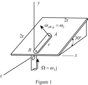
Refer to Figure 1.
Calculate the position of B with respect to A
Calculate the position of B with respect to O
Substitute
Calculate the velocity at the point
Substitute
Calculate the velocity at the point B with respect to the frame
Substitute
Calculate the acceleration at the point
Substitute
Calculate the acceleration at B with respect to the frame
Substitute
Calculate the Coriolis acceleration
Substitute
Calculate the acceleration at B
Substitute
Hence, the acceleration of B is
(b)
The acceleration of end B of the rod if
(b)
Answer to Problem 15.244P
The acceleration of end B is
Explanation of Solution
Given information:
The side length of the square plate is
The shaft rotates with a constant angular velocity as
The constant angular velocity with respect to the plate is
Calculation:
For
Sketch the Free Body Diagram of the plate, the rod AB is located at an angle
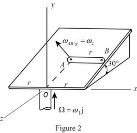
Refer to Figure 2.
Calculate the position of B with respect to A
Calculate the position of B with respect to O
Substitute
Calculate the velocity at the point
Substitute
Calculate the velocity at the point B with respect to the frame
Substitute
Calculate the acceleration at the point
Substitute
Calculate the acceleration at B with respect to the frame
Substitute
Calculate the Coriolis acceleration
Substitute
Calculate the acceleration at B
Substitute
Hence, the acceleration of B is
(c)
The acceleration of end B of the rod if
(c)
Answer to Problem 15.244P
The acceleration of end B is
Explanation of Solution
Given information:
The side of the square plate of side
The shaft rotates with a constant angular velocity
The constant angular velocity with respect to the plate is
Calculation:
For
Sketch the Free Body Diagram of the plate, the rod AB is located at an angle
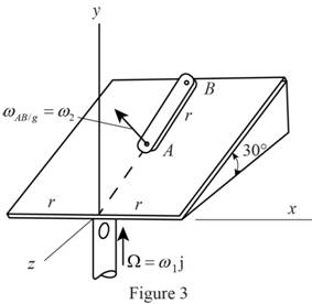
Refer to Figure 3.
Calculate the position of B with respect to A
Calculate the position of B with respect to O
Substitute
Calculate the velocity at the point
Substitute
Calculate the velocity at the point B with respect to the frame
Substitute
Calculate the acceleration at the point
Substitute
Calculate the acceleration at B with respect to the frame
Substitute
Calculate the Coriolis acceleration
Substitute
Calculate the acceleration at B
Substitute
Hence, the acceleration of B is
Want to see more full solutions like this?
Chapter 15 Solutions
Connect 2 Semester Access Card for Vector Mechanics for Engineers: Statics and Dynamics


- In Prob. 15.14, determine the velocity and acceleration of point E , assuming that the angular velocity is 26 rad/s and increases at the rate of 65 rad/s2.Reference to Problem 15.14:A circular plate of 120-mm radius is supported by two bearings A and B as shown. The plate rotates about the rod joining A and B with a constant angular velocity of 26 rad/s. Knowing that, at the instant considered, the velocity of point C is directed to the right, determine the velocity and acceleration of point E.arrow_forwardIn order to uncoil electrical wire from a spool fixed to a truck, a worker drives to the left with a speed of vA = 4 m/s. At the same time, a second worker holds the cable as he walks to the right. Knowing that at the instant shown the thickness of wire on the spool is 50 mm and that the 0.6-m-radius spool has an angular velocity of 8 rad/s, determine (a) the instantaneous center of rotation of the spool, (b) the velocity of point D on the spool, (c) the speed of the second worker B.arrow_forwardConsider that at the instant shown, bar AB of the mechanical system below has a angular velocity (wAB) counterclockwise at 5 rad/s and an angular acceleration (alphaAB)counterclockwise 2 rad/s².The length of bar AB is 0.4 m and the length of bar BC is 1 m. For the instant shown, and using a "Analysis of Relative Motion", determine: (a) the speed of point B (b) angular velocity of connecting bar BC (c) the speed of point C (d) the acceleration of point B (d) the acceleration of point Carrow_forward
- The system shown is held at rest by the brake-and-drum system shown. After the brake is partially released at t= 0 it is observed that the cylinder moves 5 m in 4.5 s. Assuming uniformly accelerated motion, determine (a) the angular acceleration of the drum, (b) the angular velocity of the drum at t= 3.5 s.arrow_forwardThe rated speed of drum B of the belt sander shown is 2400 rpm. When the power is turned off, it is observed that the sander coasts from its rated speed to rest in 10 s. Assuming uniformly decelerated motion, determine the velocity and acceleration of point C of the belt, (a) immediately before the power is turned off, (b) 9 s later.arrow_forwardA 3-in.-radius drum is rigidly attached to a 5-in.-radius drum as shown. One of the drums rolls without sliding on the surface shown, and a cord is wound around the other drum. Knowing that at the instant shown. point A has a velocity of 5.75 in./s and an acceleration of 19 in./s2, both directed to the right, determine the accelerations of points A, B, and C of the drums. a) The accelerations of point B is _ upward? b) The accelerations of point A is _ and _? (magnitude and direction) c) The accelerations of point C is _ and _? (magnitude and direction)arrow_forward
- A circular plate of 120 mm radius is supported by two bearings A and B as shown. The plate rotates about the rod joining A and B with a constant angular velocity of 26 rad/s. Knowing that, at the instant considered, the velocity of Point C is directed to the right, determine the velocity and acceleration of Point E.arrow_forwardA circular plate of 120-mm radius is supported by two bearings A and B as shown. The plate rotates about the rod joining A and B with a constant angular velocity of 26 rad/s. Knowing that, at the instant considered, the velocity of point C is directed to the right, determine the velocity and acceleration of point E.arrow_forwardA disk of radius r rolls to the right with a constant velocity v. Denoting by P the point of the rim in contact with the ground at t = 0, derive expressions for the horizontal and vertical components of the velocity of P at any time t.arrow_forward
- A series of small machine components being moved by a conveyor belt pass over a 120-mm-radius idler pulley. At the instant shown, the angular velocity of the idler pulley is 4 rad/s clockwise. Determine the angular acceleration of the pulley for which the magnitude of the total acceleration of the machine component at B is 2400 mm/s2.arrow_forwardA person walks radially inward on a platform that is rotating counterclockwise about its center. Knowing that the platform has a constant angular velocity ω and the person walks with a constant speed u relative to the platform, what is the direction of the acceleration of the person at the instant shown? a. Negative x b. Negative y c. Negative x and positive y d. Positive x and positive y e. Negative x and negative yarrow_forwardA carriage c is supported by a caster A and a cylinder B each of 60 mm diameter. Knowing that at an instant the carriage has an acceleration of 3 m/s^2 and a velocity of 2 m/s , both directed to the left , calculate the angular accelerations of the caster and of the cylinder then calculate the accelerations of the centers of the caster and of the cylinder?arrow_forward
 Elements Of ElectromagneticsMechanical EngineeringISBN:9780190698614Author:Sadiku, Matthew N. O.Publisher:Oxford University Press
 Mechanics of Materials (10th Edition)Mechanical EngineeringISBN:9780134319650Author:Russell C. HibbelerPublisher:PEARSON
 Thermodynamics: An Engineering ApproachMechanical EngineeringISBN:9781259822674Author:Yunus A. Cengel Dr., Michael A. BolesPublisher:McGraw-Hill Education
 Control Systems EngineeringMechanical EngineeringISBN:9781118170519Author:Norman S. NisePublisher:WILEY
 Mechanics of Materials (MindTap Course List)Mechanical EngineeringISBN:9781337093347Author:Barry J. Goodno, James M. GerePublisher:Cengage Learning
 Engineering Mechanics: StaticsMechanical EngineeringISBN:9781118807330Author:James L. Meriam, L. G. Kraige, J. N. BoltonPublisher:WILEY