
Statics and Mechanics of Materials Plus Mastering Engineering with Pearson eText - Access Card Package (5th Edition)
5th Edition
ISBN: 9780134301006
Author: Russell C. Hibbeler
Publisher: PEARSON
expand_more
expand_more
format_list_bulleted
Videos
Textbook Question
Chapter 15.2, Problem 15P
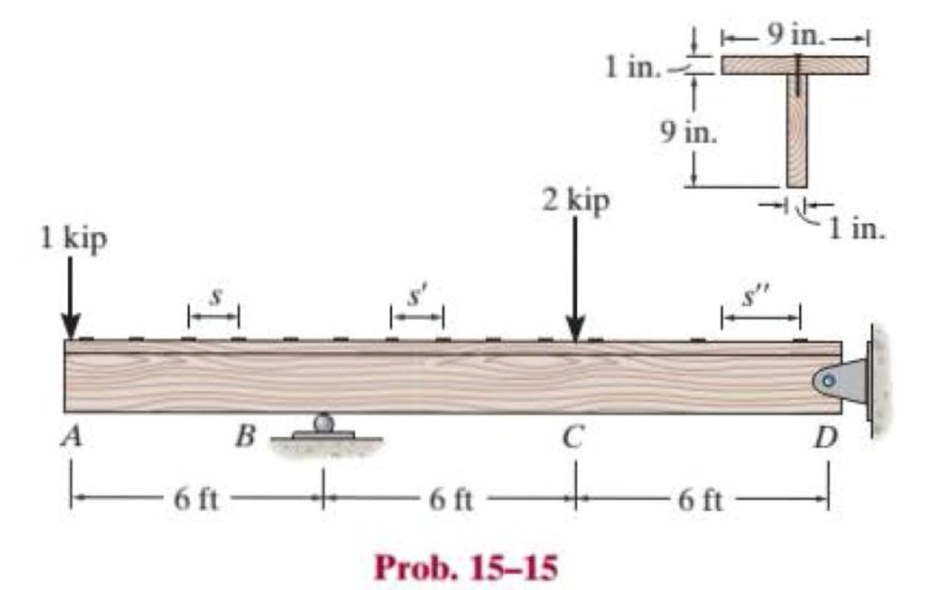
The beam is constructed from two boards. If each nail can support a shear force of 200 lb, determine the maximum spacing of the nails, s, s′, and s″, to the nearest
Expert Solution & Answer
Want to see the full answer?
Check out a sample textbook solution
Students have asked these similar questions
The beam is constructed from two boards. If each nail can support a shear force of 200 lb, determine the maximum spacing of the nails, s, s
, and s
, to the nearest 18 in. for regions AB, BC, and CD, respectively
1. Rod AB carries 500 kg cylinder at B, and it is supported by a hinge at A. Determine the minimum diameter of the bolt at A if the shear strength of the bolt is 40 MPa. Express the diameter in whole number.
A cable with supports at the same elevation has a
span of 400 m. The cable supports a uniformly distributed
load of 6 kN/m along the horizontal. The maximum ten-
sion in the cable is 5000 kN. Determine
The angle between the cable and the horizontal at a
support.
Chapter 15 Solutions
Statics and Mechanics of Materials Plus Mastering Engineering with Pearson eText - Access Card Package (5th Edition)
Ch. 15.2 - Determine the minimum dimension a to the nearest...Ch. 15.2 - Prob. 2FPCh. 15.2 - Prob. 3FPCh. 15.2 - Determine the minimum dimension h to the nearest...Ch. 15.2 - Prob. 5FPCh. 15.2 - Select the lightest W410-shaped section that can...Ch. 15.2 - The beam is made of timber that has an allowable...Ch. 15.2 - Determine the minimum width of the beam to the...Ch. 15.2 - Determine the minimum width of the beam to the...Ch. 15.2 - The brick wall exerts a uniform distributed load...
Ch. 15.2 - Select the lightest-weight wide-flange beam from...Ch. 15.2 - Prob. 6PCh. 15.2 - Select the lightest-weight wide-flange beam with...Ch. 15.2 - Select the lightest-weight wide-flange beam from...Ch. 15.2 - Select the lightest W360 wide-flange beam from...Ch. 15.2 - Investigate if the W250 58 beam can safely...Ch. 15.2 - The beam is constructed from two boards. If each...Ch. 15.2 - The joists of a floor in a warehouse are to be...Ch. 15.2 - The timber beam has a width of 6 in. Determine its...Ch. 15.2 - The beam is constructed from four boards. If each...Ch. 15.2 - The beam is constructed from two boards. If each...Ch. 15.2 - If the cable is subjected to a maximum force of P...Ch. 15.2 - If the W360 45 wide-flange beam has an allowable...Ch. 15.2 - If P = 800 lb, determine the minimum dimension a...Ch. 15.2 - If a = 3 in. and the wood has an allowable normal...Ch. 15.2 - The beam is constructed from three plastic strips....Ch. 15.2 - If the allowable bending stress is allow = 6 MPa,...Ch. 15.2 - The beam is made of Douglas fir having an...Ch. 15.2 - Select the lightest-weight wide-flange beam from...Ch. 15.2 - Draw the shear and moment diagrams for the shaft,...Ch. 15.2 - Draw the shear and moment diagrams for the shaft,...
Knowledge Booster


Learn more about
Need a deep-dive on the concept behind this application? Look no further. Learn more about this topic, mechanical-engineering and related others by exploring similar questions and additional content below.Similar questions
- For the frame shown, determine the minimum bolt diameter at B if the shearstress in the bolt is 13.053 ksiarrow_forwardIf M = 1 kip # ft, determine the resultant force the bending stresses produce on the top board A of the beam.arrow_forwardTwo identical 20-mm-thick plates are bolted to the top and bottom flange to form the built-up beam. If the beam is subjected to a shear force of V = 300 kN, determine the maximum spacing s of the bolts to the nearest mm if eachbolt has a shear strength of 30 kN.arrow_forward
- The corners of the square plate are given the displacements indicated. Determine the shear strain at A relative to axes that are directed along with AB and AD, and the shear strain at B relative to axes that are directed along with BC and BA.arrow_forward20 mm 20 mm 4. The simply supported beam on the right is built up from three boards by nailing them together as shown. If P = 12 kN, determine the maximum allowable spacing s of the nails to support the load, if each nail can resist a shear force of 1.5 kN. 1 m m B 100 mm 25 mm- 25 mm 200 mm 25 mmarrow_forwardThe beam is constructed from two boards fastened together at the top and bottom with three rows of nails spaced every 8 in. If an internal shear force of V = 800 lb is applied to the boards, determine the shear force resisted by each nail.arrow_forward
- The tool shown is made up of an oak wood part. The tool works in torsion and the allowable shear stress for the wood is 213 psi. If the wooden handle has as a minimum section a circular area of diameter 1.4, find the maximum allowable torque T. Express the result in Ib-in with a decimal approximation T D Tarrow_forwardA wooden beam is fabricated by bolting together three members as shown. The 8-mm- diameter bolts are spaced at intervals of s= 200 mm along the x axis of the beam. If the internal shear force in the beam is V=7 kN, determine the shear stress in each bolt. 40 mm 40 mm 90 mm 40 mm 300 mmarrow_forwardQ1) For the beam loaded as shown, find the magnitude and the location of the maximum shearing stress due to the shearing force. skN 80 2 kN in 100 60 4•M36KN.m R = R = 17KN 4in 6im 4in - +120mmarrow_forward
- A standard truck moves across a 25- meter span. The wheel loads are P1=36 kN and P2=142 kN separated by 4.3 m and P3=142 kN at 7.6 m from P2. Determine the beam dimensions if the maximum flexural stress is equal to 100 MPa. Use the ratio h = 1.6b. Round your answer into the nearest whole number. O 213 mm x 415 mm O 415 mm x 213 mm O 321 mm x 514 mm O 514 mm x 312 mmarrow_forwardQuestion 2: The load binder is used to support a load. An external moment, MA is applied to the handle about z axis with a magnitude of 20 Nm. a) Determine the internal moment in segment AB. b) Determine the internal shear force in segment BC. ΜΑ -300 mm 75 mm T₂arrow_forwardThe beam supports a distributed load with a maximum value of 75 lb/ft at A. Determine the resultant internal loadings, N V and M, acting on the cross section at point B.arrow_forward
arrow_back_ios
SEE MORE QUESTIONS
arrow_forward_ios
Recommended textbooks for you
 Elements Of ElectromagneticsMechanical EngineeringISBN:9780190698614Author:Sadiku, Matthew N. O.Publisher:Oxford University Press
 Mechanics of Materials (10th Edition)Mechanical EngineeringISBN:9780134319650Author:Russell C. HibbelerPublisher:PEARSON
 Thermodynamics: An Engineering ApproachMechanical EngineeringISBN:9781259822674Author:Yunus A. Cengel Dr., Michael A. BolesPublisher:McGraw-Hill Education
 Control Systems EngineeringMechanical EngineeringISBN:9781118170519Author:Norman S. NisePublisher:WILEY
 Mechanics of Materials (MindTap Course List)Mechanical EngineeringISBN:9781337093347Author:Barry J. Goodno, James M. GerePublisher:Cengage Learning
 Engineering Mechanics: StaticsMechanical EngineeringISBN:9781118807330Author:James L. Meriam, L. G. Kraige, J. N. BoltonPublisher:WILEY
Elements Of Electromagnetics
Mechanical Engineering
ISBN:9780190698614
Author:Sadiku, Matthew N. O.
Publisher:Oxford University Press
Mechanics of Materials (10th Edition)
Mechanical Engineering
ISBN:9780134319650
Author:Russell C. Hibbeler
Publisher:PEARSON
Thermodynamics: An Engineering Approach
Mechanical Engineering
ISBN:9781259822674
Author:Yunus A. Cengel Dr., Michael A. Boles
Publisher:McGraw-Hill Education
Control Systems Engineering
Mechanical Engineering
ISBN:9781118170519
Author:Norman S. Nise
Publisher:WILEY
Mechanics of Materials (MindTap Course List)
Mechanical Engineering
ISBN:9781337093347
Author:Barry J. Goodno, James M. Gere
Publisher:Cengage Learning
Engineering Mechanics: Statics
Mechanical Engineering
ISBN:9781118807330
Author:James L. Meriam, L. G. Kraige, J. N. Bolton
Publisher:WILEY
Mechanics of Materials Lecture: Beam Design; Author: UWMC Engineering;https://www.youtube.com/watch?v=-wVs5pvQPm4;License: Standard Youtube License