
Statics and Mechanics of Materials Plus Mastering Engineering with Pearson eText - Access Card Package (5th Edition)
5th Edition
ISBN: 9780134301006
Author: Russell C. Hibbeler
Publisher: PEARSON
expand_more
expand_more
format_list_bulleted
Videos
Textbook Question
Chapter 15.2, Problem 5P
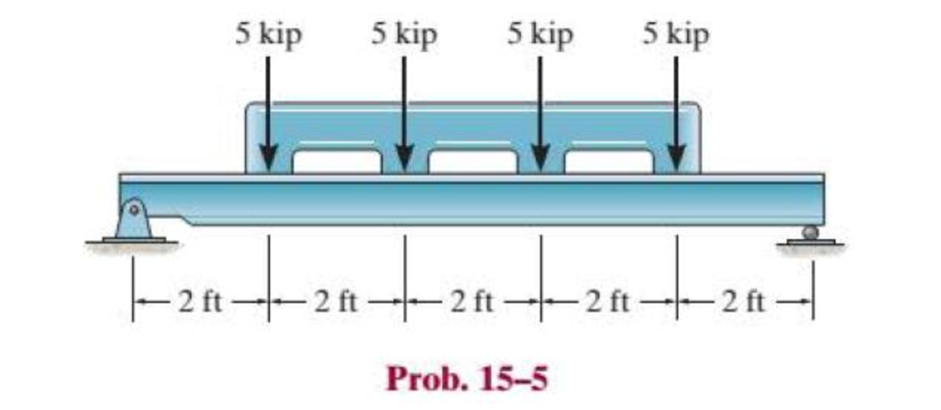
Select the lightest-weight wide-flange beam from Appendix B that will safely support the machine loading shown. The allowable bending stress is σallow = 24 ksi and the allowable shear stress is τallow = 14 ksi.
Expert Solution & Answer
Want to see the full answer?
Check out a sample textbook solution
Students have asked these similar questions
The box beam is made by nailing four 2-in. by 8-in. plankstogether as shown. Given that w0 = 300 lb/ft, find the largestallowable force P if the bending stress is limited to 1400 psi.
The simply supported joist is used in the construction of a floor for a building. In order to keep the floor low with respect to the sill beams C and D, the ends of the joists are notched as shown. If the allowable shear stress is tallow = 350 psi and the allowable bending stress is sallow = 1500 psi, determine the height h that will cause the beam to reach both allowable stresses at the same time. Also, what load P causes this to happen? Neglect the stressconcentration at the notch.
The beam has a rectangular cross-section as shown in Fig.5. (1) Draw the shear-force and bending-moment diagrams for this beam. (2) Determine the largest load P that can be supported on its overhanging ends so that the bending stress does not exceed σmax = 10 MPa.
Chapter 15 Solutions
Statics and Mechanics of Materials Plus Mastering Engineering with Pearson eText - Access Card Package (5th Edition)
Ch. 15.2 - Determine the minimum dimension a to the nearest...Ch. 15.2 - Prob. 2FPCh. 15.2 - Prob. 3FPCh. 15.2 - Determine the minimum dimension h to the nearest...Ch. 15.2 - Prob. 5FPCh. 15.2 - Select the lightest W410-shaped section that can...Ch. 15.2 - The beam is made of timber that has an allowable...Ch. 15.2 - Determine the minimum width of the beam to the...Ch. 15.2 - Determine the minimum width of the beam to the...Ch. 15.2 - The brick wall exerts a uniform distributed load...
Ch. 15.2 - Select the lightest-weight wide-flange beam from...Ch. 15.2 - Prob. 6PCh. 15.2 - Select the lightest-weight wide-flange beam with...Ch. 15.2 - Select the lightest-weight wide-flange beam from...Ch. 15.2 - Select the lightest W360 wide-flange beam from...Ch. 15.2 - Investigate if the W250 58 beam can safely...Ch. 15.2 - The beam is constructed from two boards. If each...Ch. 15.2 - The joists of a floor in a warehouse are to be...Ch. 15.2 - The timber beam has a width of 6 in. Determine its...Ch. 15.2 - The beam is constructed from four boards. If each...Ch. 15.2 - The beam is constructed from two boards. If each...Ch. 15.2 - If the cable is subjected to a maximum force of P...Ch. 15.2 - If the W360 45 wide-flange beam has an allowable...Ch. 15.2 - If P = 800 lb, determine the minimum dimension a...Ch. 15.2 - If a = 3 in. and the wood has an allowable normal...Ch. 15.2 - The beam is constructed from three plastic strips....Ch. 15.2 - If the allowable bending stress is allow = 6 MPa,...Ch. 15.2 - The beam is made of Douglas fir having an...Ch. 15.2 - Select the lightest-weight wide-flange beam from...Ch. 15.2 - Draw the shear and moment diagrams for the shaft,...Ch. 15.2 - Draw the shear and moment diagrams for the shaft,...
Knowledge Booster


Learn more about
Need a deep-dive on the concept behind this application? Look no further. Learn more about this topic, mechanical-engineering and related others by exploring similar questions and additional content below.Similar questions
- Select the lightest-weight wide-flange beam from Appendix B that will safely support the machine loading shown. The allowable bending stress is sallow = 24 ksi and the allowable shear stress is tallow = 14 ksi.arrow_forwardDraw the shear-force and bending-moment diagram for the beam shown. Assume the upward reaction provided by the ground to be uniformly distributed. Let a = 5.0 ft, b = 3.4 ft, P = 25 kips, and w = 1.1 kips/ft. Label all significant points on each diagram. Determine the maximum value of (a) the internal shear force and (b) the internal bending moment.Note that answers may be positive or negative. Here, "maximum" refers to the largest magnitude value, but you should enter your shear force and bending moment with the correct sign, using the sign convention presented in Section 7.2 of the textbook. If the magnitudes of the largest positive and largest negative values are the same, enter a positive number.arrow_forwardTwo designs for a beam are to be considered. Determine which one will support a moment of M = 140 kN . m with the least amount of bending stress. What is that stress?arrow_forward
- A 20 ft long simply supported beam has 15-inch outside diameter with 1-inch-thick circular section. The beam carries 10 lb/ft uniformly distributed load from the right support to its middle span. Another 15 lb concentrated load applied downward in the left-end support. Determine the maximum bending stress (k-lb/ft2) of the simply supported beam.arrow_forwardThe overhang beam is constructed using two 2-in. by 4-in. pieces of wood braced as shown. If the allowable bending stress is sallow = 600 psi, determine the largest load P that can be applied. Also, determine the maximum spacing of nails, s, along the beam section AC if each nail can resist a shear force of 800 lb. Assume the beam is pin connected at A, B, and D. Neglect the axial force developed in the beam along DA.arrow_forward41. The wide-flange I beam as shown is 20 ft. long. It is fixed at one end and free at the other. A twisting moment of 30,000 lb-in. is applied at the free end. If E=30×10° psi and G =12x10° psi, compute the maximum normal and shearing stresses due to bending and the maximum shearing stress due to twist. What is the angle of twist of the beam at the free end? 10.5" 1.368" 0.845" 10" prob 41arrow_forward
- To calculate the necessary height of its cross-section beam of the shape, if the maximum allowed correct stress is 12MPa and the maximum allowed shear stress is 2MPa.arrow_forwardDetermine the maximum positive normal bending stress that occurs in member ABC of the engine crane given the following information: Engine weight = 1500 lb Member ABC height (vertical cross sectional dimension) = 7 in Member ABC width (horizontal cross sectional dimension) = 1 in Express your answer to the nearest whole psi value. In your work, draw the shear and moment diagram for member ABC. For the question above, determine the maximum shear stress in member ABC that occurs between points A and B. Express your answer using the nearest whole psi value.arrow_forwardDraw the shear and moment diagram for the given loadings of beam below. Value of P = 125kN. If the maximum moment is 800 kN-m, what is the value of P?Determine the maximum flexural stress and its moment of inertia.arrow_forward
- 4. A cantilever beam 3 m long carries a concentrated load of 35 kN at its free end. The material is structural steel and the maximum bending stress is not to exceed 125 MPa. Determine the required diameter (mm) of the bar if it is circular.arrow_forwardSelect the lightest-weight wide-flange beam from Appendix B that will safely support the loading shown. The allowable bending stress sallow = 24 ksi and the allowable shear stress of tallow = 14 ksi.arrow_forward1. For the simply supported beam with a T-shape cross-section as shown below, a- Draw the shear and moments diagram of the beam. b- Determine the maximum normal bending stress and specify its location. C- If the beam made from two boards determines the maximum shear stress in the glue necessary to hold the boards together along the seam where they are joined. d- Determine the shear stress at point B. 4 m 6.5 kN/m 6m- Glue 150 mm 30 mm 150 mm 30 mmarrow_forward
arrow_back_ios
SEE MORE QUESTIONS
arrow_forward_ios
Recommended textbooks for you
 Elements Of ElectromagneticsMechanical EngineeringISBN:9780190698614Author:Sadiku, Matthew N. O.Publisher:Oxford University Press
 Mechanics of Materials (10th Edition)Mechanical EngineeringISBN:9780134319650Author:Russell C. HibbelerPublisher:PEARSON
 Thermodynamics: An Engineering ApproachMechanical EngineeringISBN:9781259822674Author:Yunus A. Cengel Dr., Michael A. BolesPublisher:McGraw-Hill Education
 Control Systems EngineeringMechanical EngineeringISBN:9781118170519Author:Norman S. NisePublisher:WILEY
 Mechanics of Materials (MindTap Course List)Mechanical EngineeringISBN:9781337093347Author:Barry J. Goodno, James M. GerePublisher:Cengage Learning
 Engineering Mechanics: StaticsMechanical EngineeringISBN:9781118807330Author:James L. Meriam, L. G. Kraige, J. N. BoltonPublisher:WILEY
Elements Of Electromagnetics
Mechanical Engineering
ISBN:9780190698614
Author:Sadiku, Matthew N. O.
Publisher:Oxford University Press
Mechanics of Materials (10th Edition)
Mechanical Engineering
ISBN:9780134319650
Author:Russell C. Hibbeler
Publisher:PEARSON
Thermodynamics: An Engineering Approach
Mechanical Engineering
ISBN:9781259822674
Author:Yunus A. Cengel Dr., Michael A. Boles
Publisher:McGraw-Hill Education
Control Systems Engineering
Mechanical Engineering
ISBN:9781118170519
Author:Norman S. Nise
Publisher:WILEY
Mechanics of Materials (MindTap Course List)
Mechanical Engineering
ISBN:9781337093347
Author:Barry J. Goodno, James M. Gere
Publisher:Cengage Learning
Engineering Mechanics: Statics
Mechanical Engineering
ISBN:9781118807330
Author:James L. Meriam, L. G. Kraige, J. N. Bolton
Publisher:WILEY
Mechanics of Materials Lecture: Beam Design; Author: UWMC Engineering;https://www.youtube.com/watch?v=-wVs5pvQPm4;License: Standard Youtube License