
Principles of Foundation Engineering (MindTap Course List)
9th Edition
ISBN: 9781337705028
Author: Braja M. Das, Nagaratnam Sivakugan
Publisher: Cengage Learning
expand_more
expand_more
format_list_bulleted
Concept explainers
Videos
Textbook Question
Chapter 16, Problem 16.3P
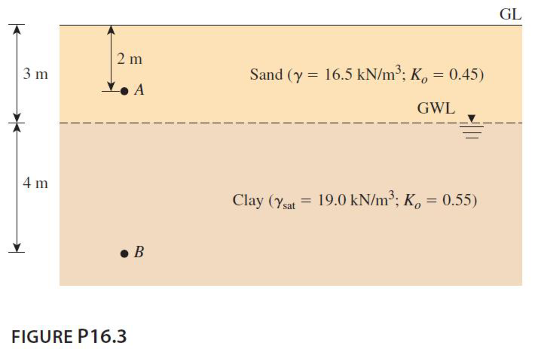
The soil profile at a site is shown Figure P16.3. Find the total horizontal normal stresses at A and B, assuming at-rest conditions.
Expert Solution & Answer

Trending nowThis is a popular solution!

Students have asked these similar questions
Refer to Figure P6.3. Determine the vertical stress increase Δσ at point A with the values q1 = 90 kN/m, q2 = 325 kN/m, x1 = 4 m, x2 = 2.5 m, and z = 3 m.
A strip load of q =53 kN/m^3 is applied over a width B =11m. Determine the increase in vertical stress in kPa at point A located z = 4.6 m below the surface. x = 8.2m
Use Eq. (6.14) to determine the stress increase Δσ at z = 10 ft below the center of the area described in Problem 6.5.
Chapter 16 Solutions
Principles of Foundation Engineering (MindTap Course List)
Knowledge Booster


Learn more about
Need a deep-dive on the concept behind this application? Look no further. Learn more about this topic, civil-engineering and related others by exploring similar questions and additional content below.Similar questions
- Referring in the Fig. 2 below, B = 6m and q =150 kPa. For Point P, z = 2m and x = 1.5m. Determine the vertical stress at Point P.arrow_forwardAn elevated structure is supported on a tripod. The legs are spaced 4 m apart and form the apexes of an equilateral triangle. Compute the increase in the vertical stress at a depth of 3m (i) beneath the point of intersection of the angular bisector (ii) beneath the centre of one of the sides of the triangle if each one of the legs carries a concentrated load of 1000Kn. Explain with diagram.arrow_forwardA flexible rectangular area 3m by 2m is subjected to a uniformly distributed load of q = 200 kN/m2. Determine the increase in vertical stress at the center at a depth of z = 3 m.arrow_forward
- Repeat Problem 10.12 for q = 700 kN/m2, B = 8 m, and z = 4 m. In this case, point A is located below the centerline under the strip load. 10.12 Refer to Figure 10.43. A strip load of q = 1450 lb/ft2 is applied over a width with B = 48 ft. Determine the increase in vertical stress at point A located z = 21 ft below the surface. Given x = 28.8 ft. Figure 10.43arrow_forwardIn Problem 16.3, if there was a surcharge of 20 kN/m2 at the ground level, what would be the total horizontal normal stresses at A and B? Use the results from Problem 16.3. 16.3 The soil profile at a site is shown Figure P16.3. Find the total horizontal normal stresses at A and B, assuming at-rest conditions.arrow_forwardA point load of 1000 kN is applied at the ground level. Plot the variation of the vertical stress increase z with depth at horizontal distances of 1 m, 2 m, and 4 m from the load.arrow_forward
- A point load of 500 kN is applied at the ground level. Plot the lateral variation of the vertical stress increase at depths of 2 m, 3 m, and 4 m below the ground level.arrow_forwardA 10 ft diameter flexible loaded area is subjected to a uniform pressure of 1200 lb/ft2. Plot the variation of the vertical stress increase beneath the center with depth z = 0 to 20 ft. In the same plot, show the variation beneath the edge of the loaded area.arrow_forwardA point load of 1000 kN is applied at the ground level. Plot the variation of the vertical stress increase Δσ with depth at horizontal distance of 1 m, 2 m, and 4 m from the load.arrow_forward
- The Two columns A and B situated 6 m apart. Column A transfers a load of 500 kN, and column B transfers a load of250 kN. Determine the resultant vertical stress increase at points vertically below the columns on a horizontalplane 2 m below the ground surface.arrow_forwardA flexible circular area of radius 3.3 m. is uniformly loaded by q = 315 kN/m². Determine the increase in vertical stress, 3.5 m. deep at its center.arrow_forwardA granular soil is subjected to a minor principal stress of 200 kN/m2. If the angle of internal friction is 30°.What is the maximum shear stress induced? a.300 b.200 c.224.2 d.173.2arrow_forward
arrow_back_ios
SEE MORE QUESTIONS
arrow_forward_ios
Recommended textbooks for you
 Principles of Foundation Engineering (MindTap Cou...Civil EngineeringISBN:9781337705028Author:Braja M. Das, Nagaratnam SivakuganPublisher:Cengage Learning
 Fundamentals of Geotechnical Engineering (MindTap...Civil EngineeringISBN:9781305635180Author:Braja M. Das, Nagaratnam SivakuganPublisher:Cengage Learning
 Principles of Geotechnical Engineering (MindTap C...Civil EngineeringISBN:9781305970939Author:Braja M. Das, Khaled SobhanPublisher:Cengage Learning
 Principles of Foundation Engineering (MindTap Cou...Civil EngineeringISBN:9781305081550Author:Braja M. DasPublisher:Cengage Learning
Principles of Foundation Engineering (MindTap Cou...
Civil Engineering
ISBN:9781337705028
Author:Braja M. Das, Nagaratnam Sivakugan
Publisher:Cengage Learning
Fundamentals of Geotechnical Engineering (MindTap...
Civil Engineering
ISBN:9781305635180
Author:Braja M. Das, Nagaratnam Sivakugan
Publisher:Cengage Learning
Principles of Geotechnical Engineering (MindTap C...
Civil Engineering
ISBN:9781305970939
Author:Braja M. Das, Khaled Sobhan
Publisher:Cengage Learning
Principles of Foundation Engineering (MindTap Cou...
Civil Engineering
ISBN:9781305081550
Author:Braja M. Das
Publisher:Cengage Learning
Stress Distribution in Soils GATE 2019 Civil | Boussinesq, Westergaard Theory; Author: Gradeup- GATE, ESE, PSUs Exam Preparation;https://www.youtube.com/watch?v=6e7yIx2VxI0;License: Standard YouTube License, CC-BY