
Loose Leaf for Engineering Circuit Analysis Format: Loose-leaf
9th Edition
ISBN: 9781259989452
Author: Hayt
Publisher: Mcgraw Hill Publishers
expand_more
expand_more
format_list_bulleted
Videos
Textbook Question
Chapter 16, Problem 30E
It is possible to construct an alternative two-port to the one shown in Fig. 16.47 by selecting appropriate parameter values as labeled on the diagram in Fig. 16.13. (a) Construct such an equivalent network. (b) Verify their equivalence with an appropriate computer simulation. (Hint: Connect some type of source(s) and load(s).)
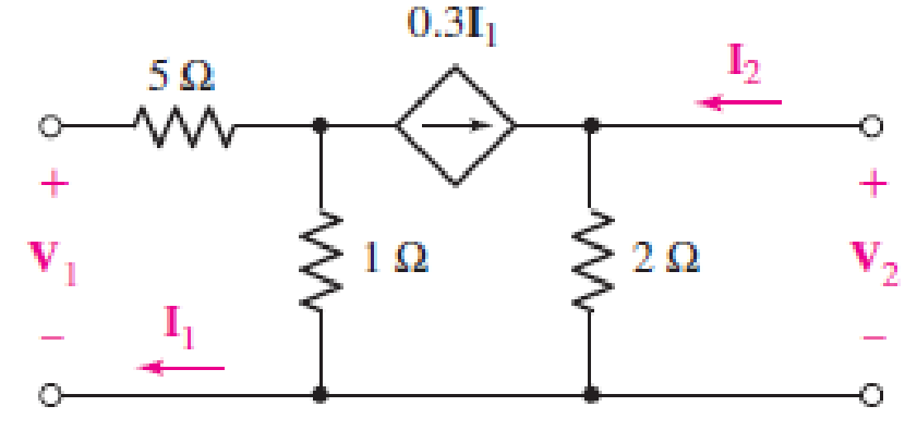
■ FIGURE 16.47
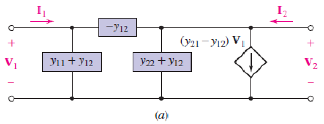
■ FIGURE 16.13
Expert Solution & Answer
Want to see the full answer?
Check out a sample textbook solution
Students have asked these similar questions
A two-port is described by the following equations: V1 = 50I1 + 10I2 and V2 = 30I1 + 20I2. Which of the following is not true?
Z12 = 10
Y12 = -0.0143
h12 = 0.5
B = 50
Note: Please write clear and answer neatly with solutions, thank you!
Find the T-parameters of a two-port device whose Z-parameters are Z11 = s, Z12 = Z21 =10s, and Z22 = 100s.
Determine the Y-parameters at a frequency of 10 kHz for the two-port network shown infigure below. Present your answer in matrix form.
Chapter 16 Solutions
Loose Leaf for Engineering Circuit Analysis Format: Loose-leaf
Ch. 16.1 - Find the input impedance of the network shown in...Ch. 16.1 - Write a set of nodal equations for the circuit of...Ch. 16.2 - By applying the appropriate 1 V sources and short...Ch. 16.2 - Prob. 4PCh. 16.2 - Prob. 5PCh. 16.3 - Prob. 6PCh. 16.3 - Use Y and Y transformations to determine Rin for...Ch. 16.4 - Find z for the two-port shown in (a) Fig. 16.23a;...Ch. 16.4 - Prob. 9PCh. 16.5 - Prob. 10P
Ch. 16.5 - Prob. 11PCh. 16.6 - Prob. 12PCh. 16 - For the following system of equations, (a) write...Ch. 16 - With regard to the passive network depicted in...Ch. 16 - Determine the input impedance of the network shown...Ch. 16 - For the one-port network represented schematically...Ch. 16 - Prob. 6ECh. 16 - Prob. 7ECh. 16 - Prob. 8ECh. 16 - Prob. 9ECh. 16 - (a) If both the op amps shown in the circuit of...Ch. 16 - Prob. 11ECh. 16 - Prob. 12ECh. 16 - Prob. 13ECh. 16 - Prob. 14ECh. 16 - Prob. 15ECh. 16 - Prob. 16ECh. 16 - Prob. 17ECh. 16 - Prob. 18ECh. 16 - Prob. 19ECh. 16 - Prob. 20ECh. 16 - For the two-port displayed in Fig. 16.49, (a)...Ch. 16 - Prob. 22ECh. 16 - Determine the input impedance Zin of the one-port...Ch. 16 - Determine the input impedance Zin of the one-port...Ch. 16 - Employ Y conversion techniques as appropriate to...Ch. 16 - Prob. 26ECh. 16 - Prob. 27ECh. 16 - Prob. 28ECh. 16 - Compute the three parameter values necessary to...Ch. 16 - It is possible to construct an alternative...Ch. 16 - Prob. 31ECh. 16 - Prob. 32ECh. 16 - Prob. 33ECh. 16 - Prob. 34ECh. 16 - The two-port networks of Fig. 16.50 are connected...Ch. 16 - Prob. 36ECh. 16 - Prob. 37ECh. 16 - Obtain both the impedance and admittance...Ch. 16 - Prob. 39ECh. 16 - Determine the h parameters which describe the...Ch. 16 - Prob. 41ECh. 16 - Prob. 42ECh. 16 - Prob. 43ECh. 16 - Prob. 44ECh. 16 - Prob. 45ECh. 16 - Prob. 46ECh. 16 - Prob. 47ECh. 16 - Prob. 48ECh. 16 - Prob. 49ECh. 16 - Prob. 50ECh. 16 - (a) Employ suitably written mesh equations to...Ch. 16 - Prob. 52ECh. 16 - Prob. 53ECh. 16 - The two-port of Fig. 16.65 can be viewed as three...Ch. 16 - Consider the two separate two-ports of Fig. 16.61....Ch. 16 - Prob. 56ECh. 16 - Prob. 57ECh. 16 - Prob. 58ECh. 16 - (a) Obtain y, z, h, and t parameters for the...Ch. 16 - Four networks, each identical to the one depicted...Ch. 16 - A cascaded 12-element network is formed using four...Ch. 16 - Prob. 62ECh. 16 - Continuing from Exercise 62, the behavior of a ray...
Additional Engineering Textbook Solutions
Find more solutions based on key concepts
A constant voltage of 10V is applied to a 50H inductance, as shown in Figure P3.51 Figure P3 51 The current in ...
Electrical Engineering: Principles & Applications (7th Edition)
How many coulombs do 93.8 1016 electrons represent?
Principles Of Electric Circuits
Design an ideal inverting op-amp circuit such that the voltage gain is Av=25 . The maximum current in any resis...
Microelectronics: Circuit Analysis and Design
Write the nodal equations for the network of Fig. 8.137 using the general approach. Find the nodal voltages usi...
Introductory Circuit Analysis (13th Edition)
When travelers from the USA and Canada visit Europe, they encounter a different power distribution system. Wall...
Electric machinery fundamentals
Three point charges of equal magnitude q, that will yield a zero net electric field at the origin.
Engineering Electromagnetics
Knowledge Booster


Learn more about
Need a deep-dive on the concept behind this application? Look no further. Learn more about this topic, electrical-engineering and related others by exploring similar questions and additional content below.Similar questions
- Using exactly seven (7) two-way MUX, implement the following function. f(w, x, y, z) = Σm(0, 1, 3, 7, 11, 13, 15arrow_forwardDESIGN A 16X1 MUX IN ORDER TO SATISFY THE FUNCTION F(A,B,C,D)=SUM(0,3,6,7,8,10,13,15) USING: B) 4X1 MULTIPLEXERSarrow_forwardExplain Adaptive XYZ Codec Using Mesh Architecture also write it's mathematical expression?arrow_forward
- Derive the expressions for the h parameters as functions of the gparameters.arrow_forwardUsing exactly seven (7) two-way MUX, implement the following function. f(w, x, y, z) = Σm(0, 1, 3, 7, 11, 13, 15) Use 7 two-way MUXsarrow_forward26 - Which of the following is true regarding Synchronous Circuits? a) O Updates are fast because they depend on instantaneous and individual propagation delays. b) O Power consumption is low. c) O Updates are common and must take longer than the slowest propagation delay available. Therefore, they are slow. d) Because memory elements are updated at different times, their design and analysis are difficult.arrow_forward
- Implement using an 8 to 1 mux. Create the truth table and create the diagram F = Σw,x,y,z(1,4,5,6,11,12,13,15).arrow_forwardSuppose two hosts, A and B, are separated by 20,000 kilometers and are connected by a direct link of R=2R=2 Mbps. Suppose the propagation speed over the link is 2.5⋅1082.5⋅108 meters/sec. Calculate the bandwidth-delay product, R⋅dpropR⋅dprop. Consider sending a file of 800,000 bits from Host A to Host B. Suppose the file is sent continuously as one large message. What is the maximum number of bits that will be in the link at any given time? Provide an interpretation of the bandwidth-delay product. What is the width (in meters) of a bit in the link? Is it longer than a football field? Derive a general expression for the width of a bit in terms of the propagation speed s, the transmission rate R, and the length of the link m.arrow_forwardDESIGN A 16X1 MUX IN ORDER TO SATISFY THE FUNCTION F(A,B,C,D)=SUM(0,3,6,7,8,10,13,15) USING: A) 8X1 MULTIPLEXERSarrow_forward
- Find the T-parameters of a two-port device whose Z-parameters are Z11 = 106 s, Z12 = Z21 =107 s, and Z22 = 108 s.arrow_forwardData Communication Suppose that Ali’s and Paul’s computers are connected by an 8 Kbps link (note, 1 Kbps = 103 bps) that uses circuit switching and that Ali sent some number of bits to Paul over the link. Suppose that circuit switching on the link connecting Ali’s and Paul’s computers is implemented using Time Division Multiplexing (TDM), that a frame is 1 sec in duration, and that a frame consists of 16 slots. Ali is assigned one slot in every frame. Considering that it took 12 minutes for Ali to send all bits to Paul, find how many bits were sent by Ali to Paul.arrow_forwardCompute the 8 – point DFT of x(n) = { 1,2,3,0,3,2,1,3}, using the following methods;(a) DIT – FFT method (b) DIF – FFT methodarrow_forward
arrow_back_ios
SEE MORE QUESTIONS
arrow_forward_ios
Recommended textbooks for you
 Introductory Circuit Analysis (13th Edition)Electrical EngineeringISBN:9780133923605Author:Robert L. BoylestadPublisher:PEARSON
 Delmar's Standard Textbook Of ElectricityElectrical EngineeringISBN:9781337900348Author:Stephen L. HermanPublisher:Cengage Learning
 Programmable Logic ControllersElectrical EngineeringISBN:9780073373843Author:Frank D. PetruzellaPublisher:McGraw-Hill Education
 Fundamentals of Electric CircuitsElectrical EngineeringISBN:9780078028229Author:Charles K Alexander, Matthew SadikuPublisher:McGraw-Hill Education
 Electric Circuits. (11th Edition)Electrical EngineeringISBN:9780134746968Author:James W. Nilsson, Susan RiedelPublisher:PEARSON
 Engineering ElectromagneticsElectrical EngineeringISBN:9780078028151Author:Hayt, William H. (william Hart), Jr, BUCK, John A.Publisher:Mcgraw-hill Education,
Introductory Circuit Analysis (13th Edition)
Electrical Engineering
ISBN:9780133923605
Author:Robert L. Boylestad
Publisher:PEARSON
Delmar's Standard Textbook Of Electricity
Electrical Engineering
ISBN:9781337900348
Author:Stephen L. Herman
Publisher:Cengage Learning
Programmable Logic Controllers
Electrical Engineering
ISBN:9780073373843
Author:Frank D. Petruzella
Publisher:McGraw-Hill Education
Fundamentals of Electric Circuits
Electrical Engineering
ISBN:9780078028229
Author:Charles K Alexander, Matthew Sadiku
Publisher:McGraw-Hill Education
Electric Circuits. (11th Edition)
Electrical Engineering
ISBN:9780134746968
Author:James W. Nilsson, Susan Riedel
Publisher:PEARSON
Engineering Electromagnetics
Electrical Engineering
ISBN:9780078028151
Author:Hayt, William H. (william Hart), Jr, BUCK, John A.
Publisher:Mcgraw-hill Education,
Introduction to Logic Gates; Author: Computer Science;https://www.youtube.com/watch?v=fw-N9P38mi4;License: Standard youtube license