Loose Leaf for Engineering Circuit Analysis Format: Loose-leaf
9th Edition
ISBN: 9781259989452
Author: Hayt
Publisher: Mcgraw Hill Publishers
bartleby

Videos

Textbook Question
Book Icon
Chapter 16, Problem 59E

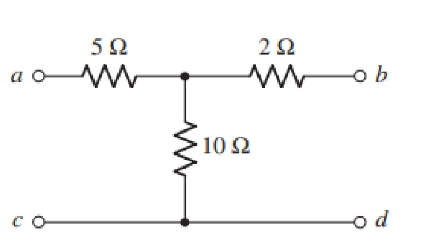
(a) Obtain y, z, h, and t parameters for the network shown in Fig. 16.67 using either the defining equations or mesh/nodal equations. (b) Verify your answers using the relationships in Table 16.1.

Chapter 16, Problem 59E, (a) Obtain y, z, h, and t parameters for the network shown in Fig. 16.67 using either the defining

(a)

Expert Solution
Check Mark
To determine

The y, z, h and t parameters for the given network.

Answer to Problem 59E

The y parameter is [0.1450.1200.1200.183]S, z parameter is [15101012]Ω, h parameter is [6.666Ω0.8330.8330.083S] and t parameter is [1.58Ω0.1S1.2].

Explanation of Solution

Given data:

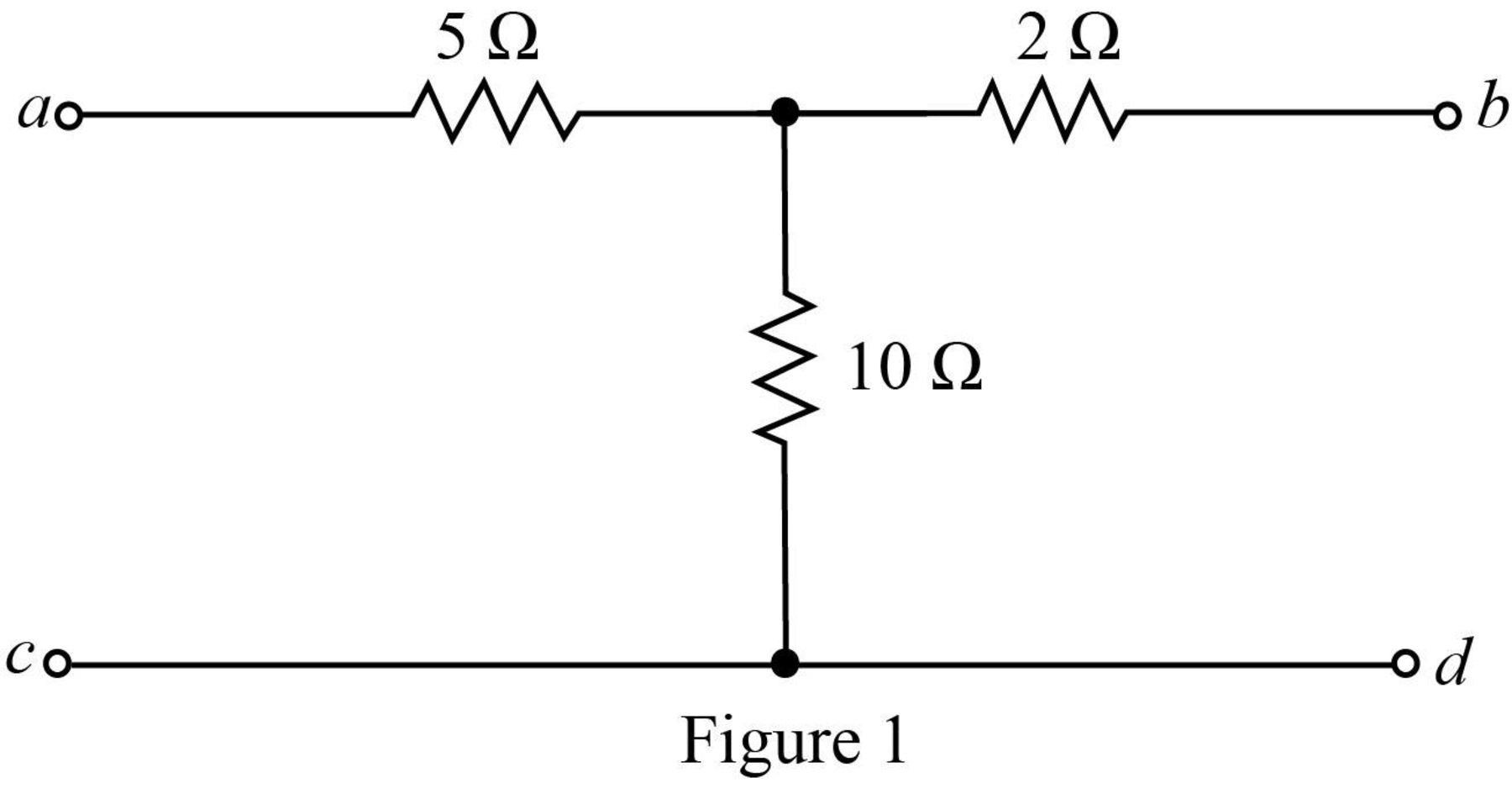
The given diagram is shown in Figure 1.

Loose Leaf for Engineering Circuit Analysis Format: Loose-leaf, Chapter 16, Problem 59E , additional homework tip  1

Calculation:

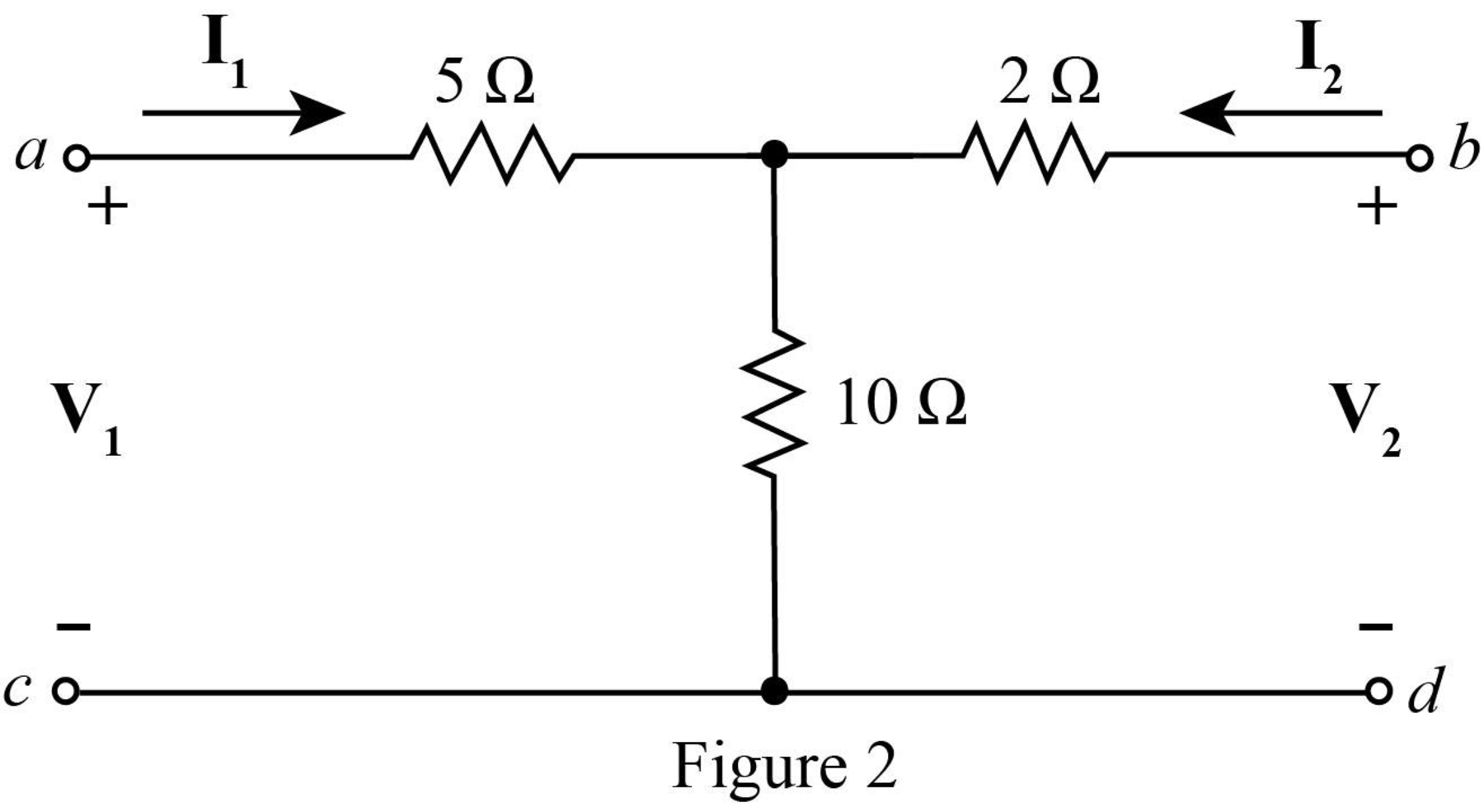
Mark the branch currents and open circuit voltages.

The required diagram is shown in Figure 2.

Loose Leaf for Engineering Circuit Analysis Format: Loose-leaf, Chapter 16, Problem 59E , additional homework tip  2

Apply KVL at the input side.

V1=5I1+10(I1+I2)V1=15I1+10I2        (1)

Apply KVL at the output side.

V2=2I2+10(I2+I1)V2=10I1+12I2        (2)

The standard equations for z parameter is written as,

V1=z11I1+z12I2        (3)

V2=z21I1+z22I2        (4)

Compare equation (1) with equation (3).

z11=15

z12=10

Compare equation (2) with equation (4).

z21=10

z22=12

The z parameter for a circuit is written as,

[z]=[z11z12z21z22]Ω

Substitute 15 for z11, 10 for z12, 10 for z21 and 12 for z22 in the above matrix.

[z]=[15101012]Ω

Rearrange equation (1) as,

I1=V110I215        (5)

Rearrange equation (2) as,

I2=V210I112        (6)

Substitute V210I112 for I2 in equation (5).

I1=V110(V210I112)15I1=12V110V2+100I112×150.455I1=0.066V10.055V2I1=0.145V10.120V2        (7)

Substitute 0.145V10.120V2 for I1 in equation (6).

I2=V210(0.145V10.120V2)12I2=1.45V1+2.20V212I2=0.120V1+0.183V2        (8)

The standard equations for y parameter is written as,

I1=y11V1+y12V2        (9)

I2=y21I1+y22I2        (10)

Compare equation (7) with equation (9).

y11=0.145

y12=0.120

Compare equation (8) with equation (10).

y21=0.120

y22=0.183

The y parameter for a circuit is written as,

[y]=[y11y12y21y22]S

Substitute 0.145 for y11, 0.120 for y12, 0.120 for y21 and 0.183 for y22 in the above matrix.

[y]=[0.1450.1200.1200.183]S

Substitute V210I112 for I2 in equation (1).

V1=15I1+10(V210I112)V1=15I1+1012V210012I1V1=6.666I1+0.833V2        (11)

The standard equations for h parameter is written as,

V1=h11I1+h12V2        (12)

I2=h21I1+h22V2        (13)

Compare equation (11) with equation (12).

h11=6.666

h12=0.833

Compare equation (6) with equation (13).

h21=1012=0.833

h22=112=0.083

The h parameter for a circuit is written as,

[h]=[h11Ωh12h21h22S]

Substitute 6.666 for h11, 0.833 for h12, 0.833 for h21 and 0.083 for h22 in the above matrix.

[h]=[6.666Ω0.8330.8330.083S]

Rearrange equation (6) as,

I2=112V21012I1I2=0.083V20.833I10.833I1=0.083V2I2I1=0.1V21.2I2        (14)

Substitute 0.1V21.2I2 for I1 in equation (1).

V1=15(0.1V21.2I2)+10I2=1.5V28I2        (15)

The standard equations for t parameter is written as,

V1=t11V2t12I2        (16)

I1=t21V2t22I2        (17)

Compare equation (15) with equation (16).

t11=1.5

t12=8

Compare equation (14) with equation (17).

t21=0.1

t22=1.2

The t parameter for the first part of the circuit is written as,

[t]=[t11t12Ωt21St22]

Substitute 1.5 for t11, 8 for t12, 0.1 for t21 and 1.2 for t22 in the above matrix.

[t]=[1.58Ω0.1S1.2]

Conclusion:

Therefore, the y parameter is [0.1450.1200.1200.183]S, z parameter is [15101012]Ω, h parameter is [6.666Ω0.8330.8330.083S] and t parameter is [1.58Ω0.1S1.2].

(b)

Expert Solution
Check Mark
To determine

To verify: The value of y, z, h and t parameters for the given network using conversions.

Explanation of Solution

Calculation:

The relation between z and y parameters is given by,

y=[z22Δzz12Δzz21Δzz11Δz]        (18)

The determinant Δz is calculated as,

|z|=|15101012|=180100=80

Substitute 15 for z11, 10 for z12, 10 for z21, 12 for z22 and 80 for Δz in equation (18).

y=[1280108010801580]=[0.150.1250.1250.1875]

The relation between z and h parameters is given by,

h=[Δzz22z12z22z21z221z22]        (19)

Substitute 15 for z11, 10 for z12, 10 for z21, 12 for z22 and 80 for Δz in equation (18).

h=[801210121012112]=[6.666Ω0.8330.8330.083S]

The relation between z and t parameters is given by,

t=[z11z21Δzz211z21z22z21]        (20)

Substitute 15 for z11, 10 for z12, 10 for z21, 12 for z22 and 80 for Δz in equation (18).

t=[151080101101210]=[1.58Ω0.1S1.2]

Conclusion:

Thus, within the limits of error the value of y, z, h and t parameters for the given network using conversions is verified.

Want to see more full solutions like this?

Subscribe now to access step-by-step solutions to millions of textbook problems written by subject matter experts!
Students have asked these similar questions
1. Consider that a third-order system has the coefficient matrices Using the method of matrix transformation obtain: a)  the Jordan canonical form (JCF) of the system and discuss whether the system is controllable or observable, accordingly. b)  the controllable canonical form (CCF) for the system. c)  the observable canonical form (OCF) for the system.
Determine the Y-parameters at a frequency of 10 kHz for the two-port network shown infigure below. Present your answer in matrix form.
Determine the chain matrix A(s) of the following 2-port.

Chapter 16 Solutions

Loose Leaf for Engineering Circuit Analysis Format: Loose-leaf

Ch. 16.5 - Prob. 11PCh. 16.6 - Prob. 12PCh. 16 - For the following system of equations, (a) write...Ch. 16 - With regard to the passive network depicted in...Ch. 16 - Determine the input impedance of the network shown...Ch. 16 - For the one-port network represented schematically...Ch. 16 - Prob. 6ECh. 16 - Prob. 7ECh. 16 - Prob. 8ECh. 16 - Prob. 9ECh. 16 - (a) If both the op amps shown in the circuit of...Ch. 16 - Prob. 11ECh. 16 - Prob. 12ECh. 16 - Prob. 13ECh. 16 - Prob. 14ECh. 16 - Prob. 15ECh. 16 - Prob. 16ECh. 16 - Prob. 17ECh. 16 - Prob. 18ECh. 16 - Prob. 19ECh. 16 - Prob. 20ECh. 16 - For the two-port displayed in Fig. 16.49, (a)...Ch. 16 - Prob. 22ECh. 16 - Determine the input impedance Zin of the one-port...Ch. 16 - Determine the input impedance Zin of the one-port...Ch. 16 - Employ Y conversion techniques as appropriate to...Ch. 16 - Prob. 26ECh. 16 - Prob. 27ECh. 16 - Prob. 28ECh. 16 - Compute the three parameter values necessary to...Ch. 16 - It is possible to construct an alternative...Ch. 16 - Prob. 31ECh. 16 - Prob. 32ECh. 16 - Prob. 33ECh. 16 - Prob. 34ECh. 16 - The two-port networks of Fig. 16.50 are connected...Ch. 16 - Prob. 36ECh. 16 - Prob. 37ECh. 16 - Obtain both the impedance and admittance...Ch. 16 - Prob. 39ECh. 16 - Determine the h parameters which describe the...Ch. 16 - Prob. 41ECh. 16 - Prob. 42ECh. 16 - Prob. 43ECh. 16 - Prob. 44ECh. 16 - Prob. 45ECh. 16 - Prob. 46ECh. 16 - Prob. 47ECh. 16 - Prob. 48ECh. 16 - Prob. 49ECh. 16 - Prob. 50ECh. 16 - (a) Employ suitably written mesh equations to...Ch. 16 - Prob. 52ECh. 16 - Prob. 53ECh. 16 - The two-port of Fig. 16.65 can be viewed as three...Ch. 16 - Consider the two separate two-ports of Fig. 16.61....Ch. 16 - Prob. 56ECh. 16 - Prob. 57ECh. 16 - Prob. 58ECh. 16 - (a) Obtain y, z, h, and t parameters for the...Ch. 16 - Four networks, each identical to the one depicted...Ch. 16 - A cascaded 12-element network is formed using four...Ch. 16 - Prob. 62ECh. 16 - Continuing from Exercise 62, the behavior of a ray...
Knowledge Booster
Background pattern image
Electrical Engineering
Learn more about
Need a deep-dive on the concept behind this application? Look no further. Learn more about this topic, electrical-engineering and related others by exploring similar questions and additional content below.
Recommended textbooks for you
Text book image
Introductory Circuit Analysis (13th Edition)
Electrical Engineering
ISBN:9780133923605
Author:Robert L. Boylestad
Publisher:PEARSON
Text book image
Delmar's Standard Textbook Of Electricity
Electrical Engineering
ISBN:9781337900348
Author:Stephen L. Herman
Publisher:Cengage Learning
Text book image
Programmable Logic Controllers
Electrical Engineering
ISBN:9780073373843
Author:Frank D. Petruzella
Publisher:McGraw-Hill Education
Text book image
Fundamentals of Electric Circuits
Electrical Engineering
ISBN:9780078028229
Author:Charles K Alexander, Matthew Sadiku
Publisher:McGraw-Hill Education
Text book image
Electric Circuits. (11th Edition)
Electrical Engineering
ISBN:9780134746968
Author:James W. Nilsson, Susan Riedel
Publisher:PEARSON
Text book image
Engineering Electromagnetics
Electrical Engineering
ISBN:9780078028151
Author:Hayt, William H. (william Hart), Jr, BUCK, John A.
Publisher:Mcgraw-hill Education,
L21E127 Control Systems Lecture 21 Exercise 127: State-space model of an electric circuit; Author: bioMechatronics Lab;https://www.youtube.com/watch?v=sL0LtyfNYkM;License: Standard Youtube License