
Videos
(a)
The determinant and the input impedance of the network when
(a)
Answer to Problem 7E
The determinant of the network is
Explanation of Solution
Given data:
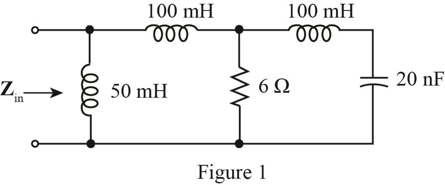
The given diagram is shown in Figure 1.
Calculation:
The conversion of
The conversion of
The conversion of
The conversion of
The conversion of
The conversion of
For
The admittance of inductor is given by,
Substitute
For
The admittance of inductor is given by,
Substitute
For
The admittance of capacitor is given by,
Substitute
For
The admittance of inductor is given by,
Substitute
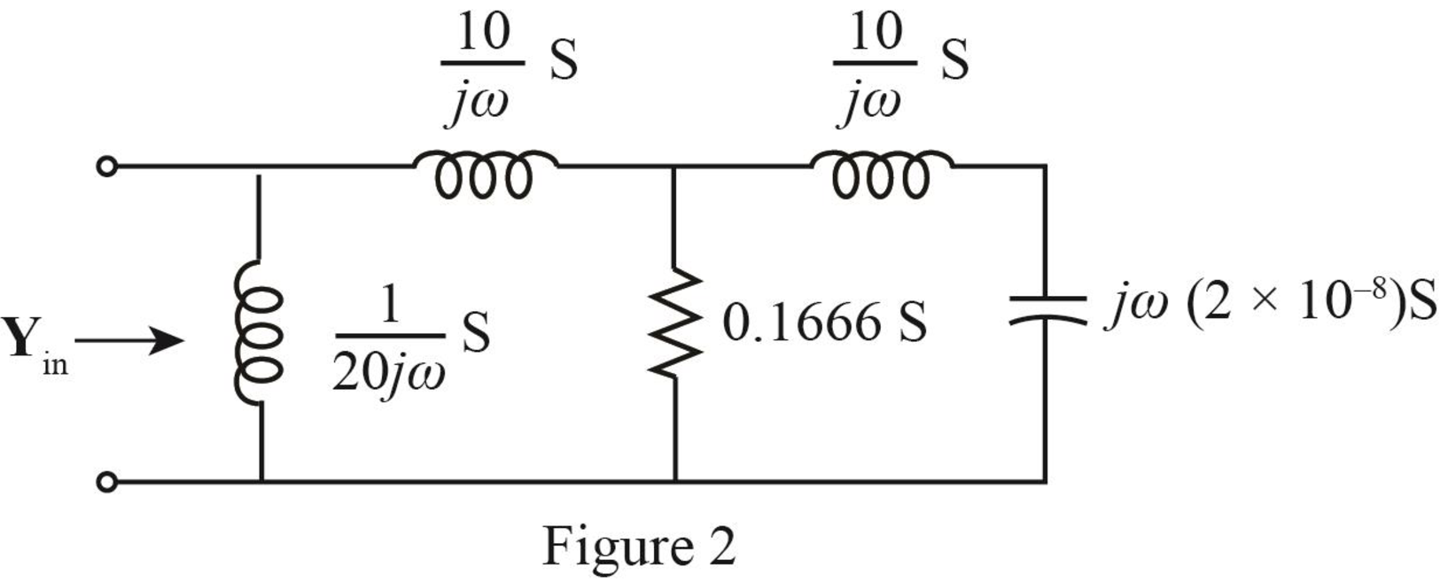
The required diagram is shown in Figure 2.
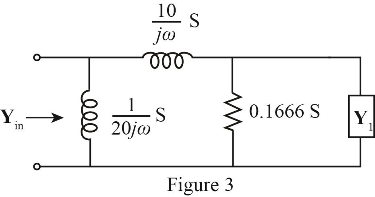
The inductor and the capacitor are in series.
The modified diagram is shown in Figure 3.
The expression for
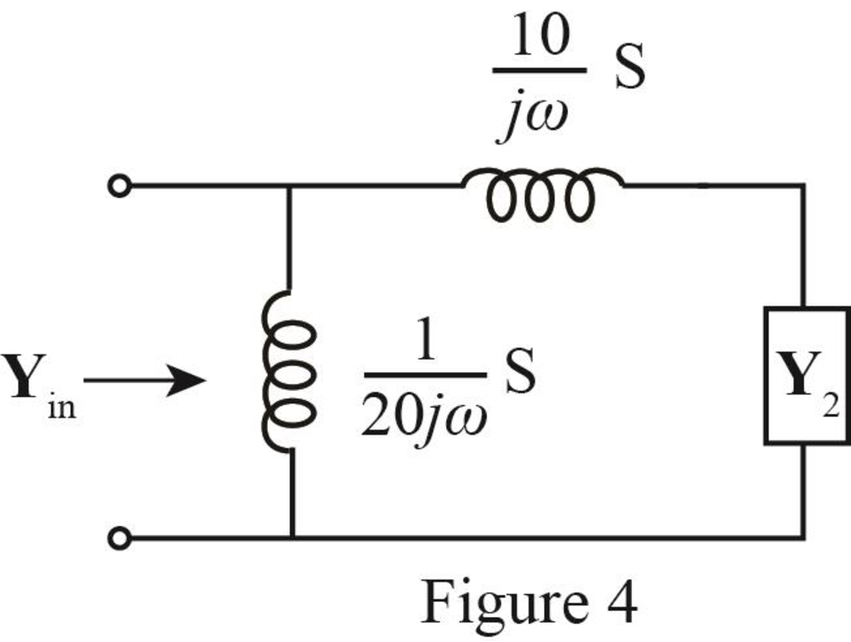
The admittance
The modified diagram is shown in Figure 4.
The expression of
The admittance
The modified diagram is shown in Figure 5.
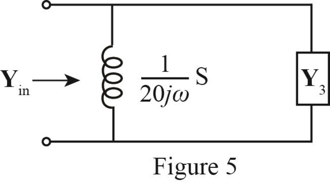
The expression of
Substitute
Further solve as,
The input admittance is the parallel combination of the inductor and
The expression of the input admittance
Substitute
Substitute
Mark the node voltages as
The required diagram is shown in Figure 6.
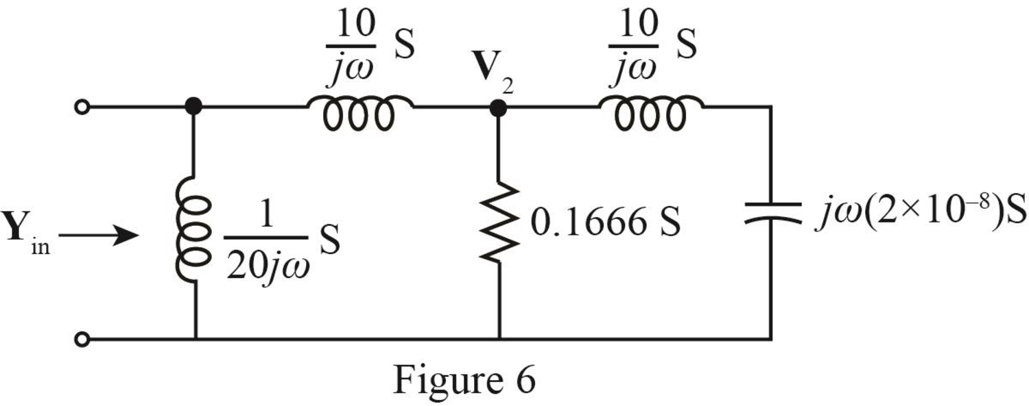
The equation at node voltage
The equation at node voltage
Substitute
Write equation (1) and (2) in matrix form.
The determinant of the given circuit is given by,
Further solve as,
Conclusion:
Therefore, the determinant of the network is,
(b)
The voltage across the current source.
(b)
Answer to Problem 7E
The voltage across the current source is
Explanation of Solution
Given data:
The value of the current source is,
The frequency is
Calculation:
The required diagram is shown in Figure 7.
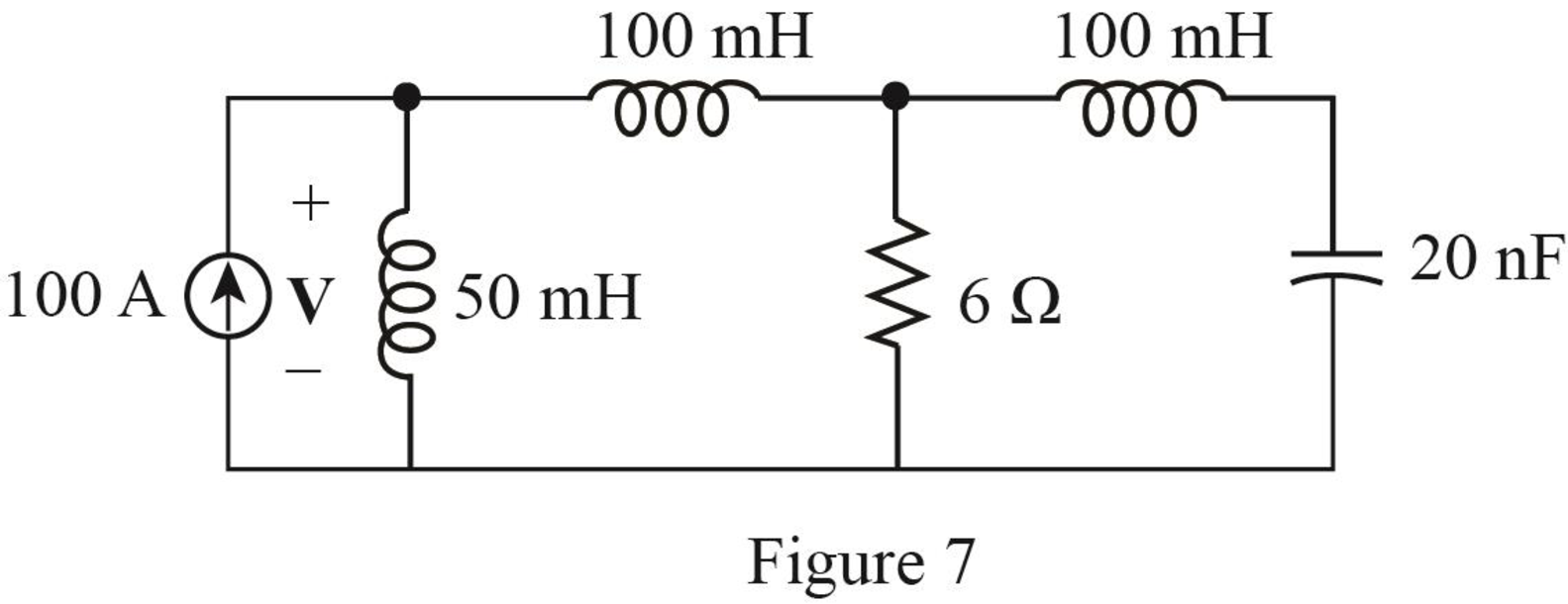
The expression for the voltage across current source is given by,
Here,
Substitute
Conclusion:
Therefore, the voltage across the current source is
Want to see more full solutions like this?
Chapter 16 Solutions
Loose Leaf for Engineering Circuit Analysis Format: Loose-leaf


- 1. Implement (2,1,3) convolutional encoder in Fig. 10.12. Give a message vector, u of arbitrary length as input to the encoder.3. Generate the output code sequence.arrow_forwardCompute the convolution y(n) = x(n) * h(n), Where x(n) = {1,1,0,1,1} and h(n) = {1,-2,-3,4), Using Tabulation method.arrow_forward20. Calculate A,B,C,D constants of a 3phase, 50Hz transmission line 160km long having the following distributed parameters R=0.15Ω/km; L= 1.20 x10⁻³ H/km; C=8x10⁻⁹ F/km; G=0arrow_forward
- The parameters of a certain transmission line operating at ω = 6×10⁸ rad/s are L = 0.35μH/m, C = 40 pF/m, G = 75 μS/m, and R = 17 Ω/m. Find α, β, λ, and Z0.arrow_forwardThe numerical input/output mean optical power ratio in a 1 km, length of optical fiber is found to be 2.5. Calculate the received mean optical power when a mean optical power of 1 mW is launched into a 5 km length of the fiber (assurning no joints or connectors).arrow_forwardAn optical fiber link with a distance of 30km long has a loss of 0.3dB/km. a) Calculate the minimum optical power level that must be launched into the fiber to maintain an optical power level of 3.0W at the receiving end.b) Estimate the required input power if the fiber has a loss of 0.6dB/km.c) Differentiate, with the aid of diagrams, the types of these dispersions and its effect on the transmission distance. (i) Modal Dispersion(ii) Chromatic Dispersion(iii) Polarization Mode Dispersionarrow_forward
- The structural engineering design section within the engineering department of a regional electrical utility corporation has developed several standard designs for a group of similar transmission line towers. The detailed design for each tower is based on one of the standard designs. A transmission line project involving 50 towers has been approved. The estimated number of engineering hours needed to accomplish the first detailed tower design is 126. Assuming a 95% learning curve, a. What is your estimate of the number of engineering hours needed to design the eighth tower and to design the last tower in the project? b. What is your estimate of the cumulative average hours required for the first five designs?arrow_forwarduse the value w=2, x=0, y=2, z=8arrow_forwardUse Norton's Theoremarrow_forward
 Introductory Circuit Analysis (13th Edition)Electrical EngineeringISBN:9780133923605Author:Robert L. BoylestadPublisher:PEARSON
 Delmar's Standard Textbook Of ElectricityElectrical EngineeringISBN:9781337900348Author:Stephen L. HermanPublisher:Cengage Learning
 Programmable Logic ControllersElectrical EngineeringISBN:9780073373843Author:Frank D. PetruzellaPublisher:McGraw-Hill Education
 Fundamentals of Electric CircuitsElectrical EngineeringISBN:9780078028229Author:Charles K Alexander, Matthew SadikuPublisher:McGraw-Hill Education
 Electric Circuits. (11th Edition)Electrical EngineeringISBN:9780134746968Author:James W. Nilsson, Susan RiedelPublisher:PEARSON
 Engineering ElectromagneticsElectrical EngineeringISBN:9780078028151Author:Hayt, William H. (william Hart), Jr, BUCK, John A.Publisher:Mcgraw-hill Education,