Concept explainers
Videos
(a)
The angular acceleration of the gear
Answer to Problem 16.36P
The angular acceleration of the gear
Explanation of Solution
Given Information:
The mass of the gear
Write the expression for the tangential acceleration of the gear teeth.
Here, the angular acceleration is
Write the expression for the tangential acceleration of the gear
Here, the angular acceleration of gear
Write the expression for the tangential acceleration of the gear
Here, the angular acceleration of gear
Write the expression for the tangential acceleration of the gear
Here, the angular acceleration of gear
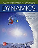
Draw the free body diagram for the gear
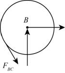
Figure-(1)
Draw the kinetic diagram of the gear
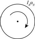
Figure-(2)
Write the expression for the moment of inertia gear
Here, the mass of the gear
Write the expression for the external moment at
Here, the tangential force exerted by gear
Write the expression for the effective forces using the Figure-(2).
Since, the system of external forces is equivalent to system of effective forces hence
Substitute
Draw the free body diagram for the gear
Figure-(3)
Draw the kinetic diagram for the gear
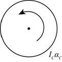
Figure-(4)
Write the expression for the moment of inertia gear
Here, the mass of the gear is
Write the expression for the external moment at
Here, the tangential force exerted by gear
Write the expression for the effective forces using the Figure-(4).
Since, the system of external forces is equivalent to system of effective forces hence
Substitute
Draw the free body diagram for the gear
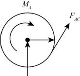
Figure-(5)
Draw the kinetic diagram of the gear
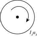
Figure-(6) Write the expression for the moment of inertia gear
Here, the mass of the gear is
Write the expression for the external moment at
Here, the couple force applied on the gear
Write the expression for the effective forces using the Figure-(6).
Since, the system of external forces is equivalent to system of effective forces hence
Substitute
Calculation:
Substitute
Substitute
Substitute
The tangential acceleration of the gear
Substitute
The tangential acceleration of the gear
Substitute
Substitute
Substitute
Substitute
Substitute
Substitute
Substitute
Substitute
Substitute
Conclusion:
The angular acceleration of the gear
(b)
The tangential force exerted by gear
Answer to Problem 16.36P
The tangential force exerted by gear
Explanation of Solution
Write the expression for the tangential force exerted by gear
Calculation:
Substitute
Conclusion:
The tangential force exerted by gear
Want to see more full solutions like this?
Chapter 16 Solutions
Package: Vector Mechanics For Engineers: Dynamics With 1 Semester Connect Access Card


- The steel roll shown has a mass of 1200 kg, has a centroidal radius of gyration of 150 mm, and is lifted by two cables looped around its shaft. Knowing that at the instant shown the acceleration of the roll is 150 mm/s2 downward and that for each cable TA = 3000 N, determine (a) the corresponding tension TB, (b) the angular acceleration of the roll.arrow_forwardThe shutter shown was formed by removing one quarter of a disk of 0.75-in. radius and is used to interrupt a beam of light emanating from a lens at C. Knowing that the shutter weighs 0.125 lb and rotates at the constant rate of 24 cycles per second, determine the magnitude of the force exerted by the shutter on the shaft at Aarrow_forwardThe 10-in.-radius brake drum is attached to a larger flywheel which is not shown. The total mass moment of inertia of the flywheel and drum is 22 lb ⋅ ft ⋅ s 2 and the coefficient of kinetic friction between the drum and the brake shoe is 0.41. Knowing that the initial angular velocity is 255 rpm clockwise, determine the force which must be exerted by the hydraulic cylinder at point B if the system is to stop in 85 revolutions. DO NOT ROUND OFF IN THE SOLUTION. ROUND OFF ONLY THE FINAL ANSWERarrow_forward
- A uniform 144-lb cube is attached to a uniform 136-lb circular shaft as shown, and a couple M with a constant magnitude is applied to the shaft when the system is at rest. Knowing that r = 4 in., L= 12 in., and the angular velocity of the system is 960 rpm after 4 s, determine the magnitude of the couple M.arrow_forwardThe 4-kg uniform slender bar BD is attached to bar AB and a wheel of negligible mass that rolls on a circular surface. Knowing that at the instant shown bar AB has an angular velocity of 6 rad/s and no angular acceleration, determine the reaction at point D.arrow_forwardThe double pulley shown has a mass of 3 kg and a radius of gyration of 100 mm. Knowing that when the pulley is at rest, a force P of magnitude 24 N is applied to cord B, determine (a) the velocity of the center of the pulley after 1.5 s,(b) the tension in cord C.arrow_forward
- A thin disk of mass m = 4 kg rotates with an angular velocity w2 with respect to arm ABC, which itself rotates with an angular velocity w1 about the y axis. Knowing that w1 = 5 rad/s and w2 = 15 rad/s and that both are constant, determine the force-couple system representing the dynamic reaction at the support at A.arrow_forwardA uniform disk of mass m = 4 kg and radius r = 150 mm is supported by a belt ABCD that is bolted to the disk at B and C. If the belt suddenly breaks at a point located between A and B, draw the FBD and KD for the disk immediately after the break.arrow_forwardThe 10-in.-radius brake drum is attached to a larger flywheel which is not shown. The total mass moment of inertia of the flywheel and drum is 22 lb ⋅ ft ⋅ s 2 and the coefficient of kinetic friction between the drum and the brake shoe is 0.41. Knowing that the initial angular velocity is 255 rpm clockwise, determine the force which must be exerted by the hydraulic cylinder at point B if the system is to stop in 85 revolutions. determine the force which must be exerted by the hydraulic cylinder at point B if the system is to stop in 85 revolutions. DO NOT ROUND OFF IN THE SOLUTION. ROUND OFF ONLY IN 2 DECIMAL PLACE IN THE FINAL ANSWER.arrow_forward
- The 8-in. radius brake drum is attached to a larger flywheel that is not shown. The total mass moment of inertia of the drum and the flywheel is 15 lb.ft.s2 and the coefficient of kinetic friction between the drum and the brake shoe is 0.40. Knowing that the angular velocity of the flywheel is 450 rpm clockwise when a force P of magnitude 65 lbf. is applied to the pedal C, determine the number of the revolutions executed by the flywheel before it comes to rest. (The final answer should be in two decimal places with correct units)arrow_forwardTwo identical 4-lb slender rods AB and BC are connected by a pin at B and by the cord AC. The assembly rotates in a vertical plane under the combined effect of gravity and a 6-lb·ft couple M applied to rod AB. Knowing that in the position shown the angular velocity of the assembly is zero, determine (a) the angular acceleration of the assembly, (b) the tension in cord AC.arrow_forwardThe 10-in.-radius brake drum is attached to a larger flywheel which is not shown. The total mass moment of inertia of the flywheel and drum is 22 lb ⋅ ft ⋅ s 2 and the coefficient of kinetic friction between the drum and the brake shoe is 0.41. Knowing that the initial angular velocity is 255 rpm clockwise, determine the force which must be exerted by the hydraulic cylinder at point B if the system is to stop in 85 revolutions.arrow_forward
 Elements Of ElectromagneticsMechanical EngineeringISBN:9780190698614Author:Sadiku, Matthew N. O.Publisher:Oxford University Press
 Mechanics of Materials (10th Edition)Mechanical EngineeringISBN:9780134319650Author:Russell C. HibbelerPublisher:PEARSON
 Thermodynamics: An Engineering ApproachMechanical EngineeringISBN:9781259822674Author:Yunus A. Cengel Dr., Michael A. BolesPublisher:McGraw-Hill Education
 Control Systems EngineeringMechanical EngineeringISBN:9781118170519Author:Norman S. NisePublisher:WILEY
 Mechanics of Materials (MindTap Course List)Mechanical EngineeringISBN:9781337093347Author:Barry J. Goodno, James M. GerePublisher:Cengage Learning
 Engineering Mechanics: StaticsMechanical EngineeringISBN:9781118807330Author:James L. Meriam, L. G. Kraige, J. N. BoltonPublisher:WILEY