
EBK STATICS AND MECHANICS OF MATERIALS
5th Edition
ISBN: 8220102955295
Author: HIBBELER
Publisher: PEARSON
expand_more
expand_more
format_list_bulleted
Concept explainers
Videos
Textbook Question
Chapter 16.2, Problem 15P
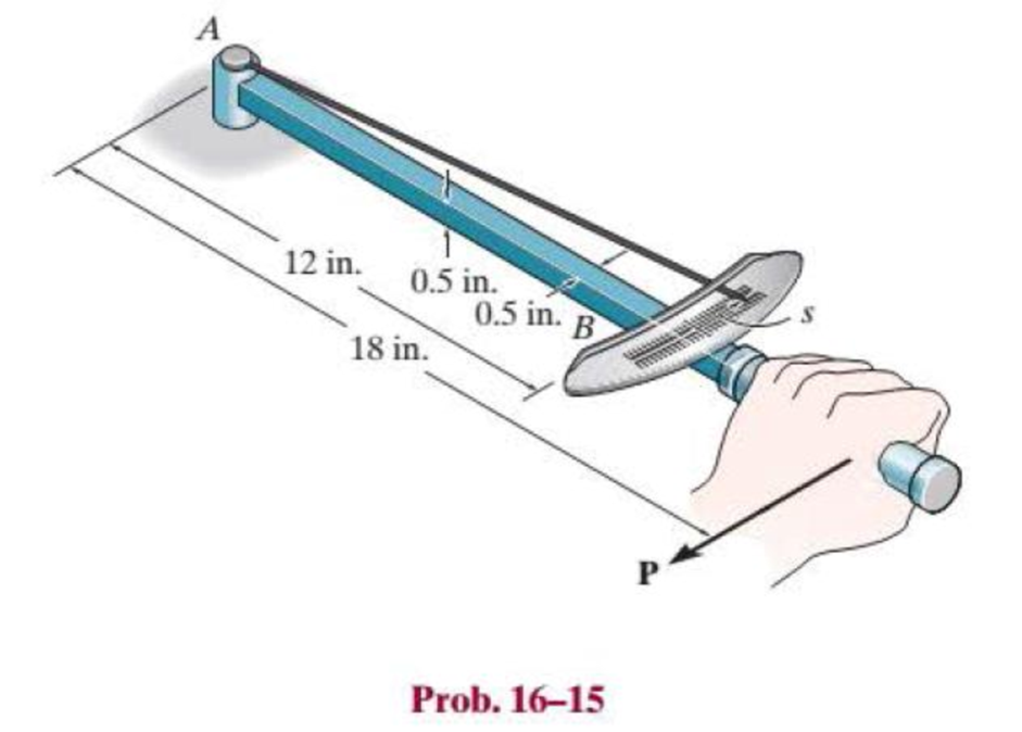
A torque wrench is used to tighten the nut on a bolt. If the dial indicates that a torque of 60 lb · ft is applied when the bolt is fully tightened, determine the force P acting at the handle and the distance s the needle moves along the scale. Assume only the portion AB of the beam distorts. The cross section is square having dimensions of 0.5 in. by 0.5 in. E = 29(103) ksi.
Expert Solution & Answer
Want to see the full answer?
Check out a sample textbook solution
Students have asked these similar questions
The rigid bar AB and CD are supported by pins at A and D. the vertical rods are made of aluminum and bronze. Determine the vertical displacement of the point where the force P= 10 kips is applied. Neglect the weight of the members.
The steel bars AC and BC, each of cross-sectional area 120 mm2, are joined at C with a Determine the displacement of point C caused by the 15-kN load. Use E = 200 GPa for steel.
The assembly below consists of a steel rod CB and an aluminium rod BA, each having a diameter of 12 mm.
If the rod is subjected to the axial loadings at A and at the coupling B, determine the displacement of the coupling B and the end A.
The unstretched length of each segment is shown below. Neglect the size of the connections at B and C, and assume that they are rigid. Est = 200 GPa, Eal = 70 GPa.
Chapter 16 Solutions
EBK STATICS AND MECHANICS OF MATERIALS
Ch. 16.2 - In each ease, determine the internal bending...Ch. 16.2 - Prob. 1FPCh. 16.2 - Determine the slope and deflection of end A of the...Ch. 16.2 - Prob. 3FPCh. 16.2 - Prob. 4FPCh. 16.2 - Determine the maximum deflection of the simply...Ch. 16.2 - Prob. 6FPCh. 16.2 - An L2 steel strap having a thickness of 0.125 in....Ch. 16.2 - The L2 steel blade of the band saw wraps around...Ch. 16.2 - A picture is taken of a man performing a pole...
Ch. 16.2 - Determine the equation of the elastic curve for...Ch. 16.2 - Determine the deflection of end C of the...Ch. 16.2 - Prob. 6PCh. 16.2 - The A-36 steel beam has a depth of 10 in. and is...Ch. 16.2 - Prob. 8PCh. 16.2 - Determine the equations of the elastic curve for...Ch. 16.2 - Determine the equations of the elastic curve using...Ch. 16.2 - Determine the equations of the elastic curve using...Ch. 16.2 - Prob. 12PCh. 16.2 - Determine the maximum deflection of the beam and...Ch. 16.2 - The simply supported shaft has a moment of inertia...Ch. 16.2 - A torque wrench is used to tighten the nut on a...Ch. 16.2 - The pipe can be assumed roller supported at its...Ch. 16.2 - Determine the equations of the elastic curve for...Ch. 16.2 - The bar is supported by a roller constraint at B,...Ch. 16.2 - The bar is supported by a roller constraint at B,...Ch. 16.2 - Determine the equations of the elastic curve using...Ch. 16.2 - Prob. 21PCh. 16.2 - Determine the elastic curve for the cantilevered...Ch. 16.2 - Prob. 23PCh. 16.2 - Prob. 24PCh. 16.2 - The floor beam of the airplane is subjected to the...Ch. 16.2 - Determine the maximum deflection of the simply...Ch. 16.2 - The beam is made of a material having a specific...Ch. 16.2 - Determine the slope at end B and the maximum...Ch. 16.2 - Prob. 29PCh. 16.2 - Determine the equations of the elastic curve using...Ch. 16.3 - The shaft is supported at A by a journal bearing...Ch. 16.3 - The shaft supports the two pulley loads shown....Ch. 16.3 - Prob. 33PCh. 16.3 - Prob. 34PCh. 16.3 - The beam is subjected to the load shown. Determine...Ch. 16.3 - Prob. 36PCh. 16.3 - Determine the equation of the elastic curve and...Ch. 16.3 - Prob. 38PCh. 16.3 - Prob. 39PCh. 16.3 - Determine the slope at A and the deflection of end...Ch. 16.3 - Determine the maximum deflection in region AB of...Ch. 16.3 - Prob. 42PCh. 16.3 - Prob. 43PCh. 16.3 - Prob. 44PCh. 16.4 - The W10 15 cantilevered beam is made of A-36...Ch. 16.4 - The W10 15 cantilevered beam is made of A-36...Ch. 16.4 - The W14 43 simply supported beam is made of A992...Ch. 16.4 - The W14 43 simply supported beam is made of A992...Ch. 16.4 - The W14 43 simply supported beam is made of A-36...Ch. 16.4 - The W14 43 simply supported beam is made of A-36...Ch. 16.4 - The W8 48 cantilevered beam is made of A-36 steel...Ch. 16.4 - The beam supports the loading shown. Code...Ch. 16.4 - Prob. 53PCh. 16.4 - The W8 48 cantilevered beam is made of A-36 steel...Ch. 16.4 - Prob. 55PCh. 16.4 - Prob. 56PCh. 16.4 - Prob. 57PCh. 16.4 - The assembly consists of a cantilevered beam CB...Ch. 16.4 - Prob. 59PCh. 16.4 - Prob. 60PCh. 16.5 - Determine the reactions at the fixed support A and...Ch. 16.5 - Prob. 8FPCh. 16.5 - Determine the reactions at the fixed support A and...Ch. 16.5 - Prob. 10FPCh. 16.5 - Prob. 11FPCh. 16.5 - Prob. 12FPCh. 16.5 - Prob. 61PCh. 16.5 - Determine the reactions at the supports, then draw...Ch. 16.5 - Determine the reactions at the supports, then draw...Ch. 16.5 - Prob. 64PCh. 16.5 - The beam is used to support the 20-kip load....Ch. 16.5 - Prob. 66PCh. 16.5 - Determine the reactions at the supports A and B....Ch. 16.5 - Before the uniform distributed load is applied to...Ch. 16.5 - Prob. 69PCh. 16.5 - Prob. 70PCh. 16.5 - The beam is supported by the bolted supports at...Ch. 16.5 - Prob. 72PCh. 16.5 - Prob. 73PCh. 16 - Prob. 1RPCh. 16 - Draw the bending-moment diagram for the shaft and...Ch. 16 - Prob. 3RPCh. 16 - Determine the equations of the elastic curve for...Ch. 16 - Determine the maximum deflection between the...Ch. 16 - Prob. 6RPCh. 16 - The framework consists of two A-36 steel...Ch. 16 - Prob. 8RPCh. 16 - Using the method of superposition, determine the...
Knowledge Booster


Learn more about
Need a deep-dive on the concept behind this application? Look no further. Learn more about this topic, mechanical-engineering and related others by exploring similar questions and additional content below.Similar questions
- Solve Prob. 7.29 if =0.arrow_forwardThe assembly consists of a steel rod CB and an aluminum rod BA, each having a diameter of 15 mm. The rod is subjected to the axial loadings at A and at the coupling B. If after applying the load coupling B displaced 1.1 mm to the right, determine the change in the dimension of the cross section of steel rod CB. The unstretched length of each segment is shown in the figure. Neglect the size of the connections at B and C, and assume that they are rigid. Est = 200 GPa Vst = 0.32 %3D В A 20 kN 7 kN 3 m - 2 m·arrow_forwardThe truss is made of three A-36 steel members, each having a cross-sectional area of 400 mm2. Determine the horizontal displacement of the roller at C when P = 8 kN.arrow_forward
- Determine the internal forces (axial force, shear force, and bending moment) at point j of the indicated structure, teta = 90 º,arrow_forwardThe 10-mm-diameter bolt is made of an aluminum alloy. It fits through a magnesium sleeve that has an inner diameter of 15 mm and an outer diameter of 25 mm. The original lengths of the bolt and sleeve are 80 mm and 50 mm, respectively. If after the nut on the bolt is tightened the tension in the bolt is 10 kN, determine the change in dimension of the cross-section of the bolt and the sleeve. Assume the material at A is rigid. E = 70 GPa, Emg = 45 GPa, Ga = 26 GPa, Gmg = 17 GPa.arrow_forwardThe blade of the hacksaw is subjected to a pretension force of F = 100 N. Determine the resultant internal loadings acting on section a–a that passes through point D.arrow_forward
- The shaft is made from a solid steel section AB and a tubular portion made of steel and having a brass core. If it is fixed to a rigid support at A, and a torque of T = 50 lb.ft is applied to it at C, determine the rotation angle that occurs at C relative to A and compute the maximum shear stress and maximum shear strain in the brass and steel. Take Gst = 11500 ksi, Gbr = 5600 Ksi. 3 ft 0.5 in. B 1 in. T = 50 lb•ftarrow_forwardDetermine the x-y and n-t components of the 31-kip force Facting on the simply-supported beam. F = 31 kips L 18' B 25' 14° 43 C ∙narrow_forwardUsing the same figure, determine the components of force F along X-Y axes which are parallel and perpendicular to the incline. F = 260lbs 12 F, = Fr Y 5 P = 361lbs 12 3 4arrow_forward
- Determine the smallest allowable diameter of the shaft which is subjected to the concentrated forces. The journal bearing at A and B only support vertical forces. The allowable bending stress is σallow= 160 MPa Bearing A only receives forces in the radial direction of the bearing. Bearing B is a steering bearing and also carries longitudinal loads on the shaft. F1= 10kN F2=23 kN L1=420 mm L2= 310mm L3=540mmarrow_forwardThe metal stud punch is subjected to a force of 120 N on the handle. determine the magnitude of the reactive force at the pin A and in the short link BC. Also, determine the resultant internal loadings acting on the cross section at point D.arrow_forwardDetermine the largest internal normal force in the bar.arrow_forward
arrow_back_ios
SEE MORE QUESTIONS
arrow_forward_ios
Recommended textbooks for you
 International Edition---engineering Mechanics: St...Mechanical EngineeringISBN:9781305501607Author:Andrew Pytel And Jaan KiusalaasPublisher:CENGAGE L
International Edition---engineering Mechanics: St...
Mechanical Engineering
ISBN:9781305501607
Author:Andrew Pytel And Jaan Kiusalaas
Publisher:CENGAGE L
Types Of loads - Engineering Mechanics | Abhishek Explained; Author: Prime Course;https://www.youtube.com/watch?v=4JVoL9wb5yM;License: Standard YouTube License, CC-BY