
EBK STATICS AND MECHANICS OF MATERIALS
5th Edition
ISBN: 8220102955295
Author: HIBBELER
Publisher: PEARSON
expand_more
expand_more
format_list_bulleted
Videos
Textbook Question
Chapter 16.4, Problem 52P
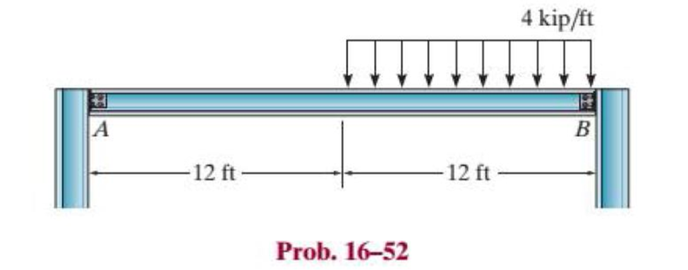
The beam supports the loading shown. Code restrictions, due to a plaster ceiling, require the maximum deflection not to exceed 1/360 of the span length. Select the lightest-weight A-36 steel wide-flange beam from Appendix B that will satisfy this requirement and safely support the load. The allowable bending stress is σallow = 24 ksi and the allowable shear stress is τallow = 14 ksi. Assume A is a roller and B is a pin.
Expert Solution & Answer
Want to see the full answer?
Check out a sample textbook solution
Students have asked these similar questions
The cantilever beam shown is subjected to a concentrated load of P=70800 lb. The cross-sectional dimensions and the moment of
inertia of the W16x57 wide-flange shape are:
d = 16.4 in.
tw=0.430 in.
by=7.12 in.
ty=0.715 in.
1₂-758 in.4
Compute the value of the shear stress at point H, located at y = 4.8 in. below the centroidal xis.
H
Answer: Shear stress =
psi
QUESTION 3
If the allowable bending stresses for a beam in one application is 6 kip/in2 in tension. The cross-section of the beam is W8 x 40.
If the beam is 10 foot long and simply supported and has a concentrated load applied at x = 3 ft as shown below.
• Generate the shear force and bending moment diagram in terms of P;
• Based on the allowable maximum bending moment you just obtained above, calculate/ input the mazimm allowable value of the load P:
please, pay attention to units, and calculate your answer to 1 decimal place..
3 ft
7 ft
kip.
AWT305 x 41 standard steel shape is used to support the loads shown on the beam. The dimensions from the top and bottom of the
shape to the centroidal axis are shown in the sketch of the cross section. Assume LAB = 3 m, LBC= 6 m, LCD= 4 m, PA = 10 kN, WBC = 7
kN/m. Consider the entire 13-m length of the beam and determine:
(a) the maximum tension bending stress or at any location along the beam, and
(b) the maximum compression bending stress oc at any location along the beam.
A
PA
LAB
B
WBC
LBC
T
WT305 x 41
LCD
↑
88.9 mm.
211.1 mm
D
X
Chapter 16 Solutions
EBK STATICS AND MECHANICS OF MATERIALS
Ch. 16.2 - In each ease, determine the internal bending...Ch. 16.2 - Prob. 1FPCh. 16.2 - Determine the slope and deflection of end A of the...Ch. 16.2 - Prob. 3FPCh. 16.2 - Prob. 4FPCh. 16.2 - Determine the maximum deflection of the simply...Ch. 16.2 - Prob. 6FPCh. 16.2 - An L2 steel strap having a thickness of 0.125 in....Ch. 16.2 - The L2 steel blade of the band saw wraps around...Ch. 16.2 - A picture is taken of a man performing a pole...
Ch. 16.2 - Determine the equation of the elastic curve for...Ch. 16.2 - Determine the deflection of end C of the...Ch. 16.2 - Prob. 6PCh. 16.2 - The A-36 steel beam has a depth of 10 in. and is...Ch. 16.2 - Prob. 8PCh. 16.2 - Determine the equations of the elastic curve for...Ch. 16.2 - Determine the equations of the elastic curve using...Ch. 16.2 - Determine the equations of the elastic curve using...Ch. 16.2 - Prob. 12PCh. 16.2 - Determine the maximum deflection of the beam and...Ch. 16.2 - The simply supported shaft has a moment of inertia...Ch. 16.2 - A torque wrench is used to tighten the nut on a...Ch. 16.2 - The pipe can be assumed roller supported at its...Ch. 16.2 - Determine the equations of the elastic curve for...Ch. 16.2 - The bar is supported by a roller constraint at B,...Ch. 16.2 - The bar is supported by a roller constraint at B,...Ch. 16.2 - Determine the equations of the elastic curve using...Ch. 16.2 - Prob. 21PCh. 16.2 - Determine the elastic curve for the cantilevered...Ch. 16.2 - Prob. 23PCh. 16.2 - Prob. 24PCh. 16.2 - The floor beam of the airplane is subjected to the...Ch. 16.2 - Determine the maximum deflection of the simply...Ch. 16.2 - The beam is made of a material having a specific...Ch. 16.2 - Determine the slope at end B and the maximum...Ch. 16.2 - Prob. 29PCh. 16.2 - Determine the equations of the elastic curve using...Ch. 16.3 - The shaft is supported at A by a journal bearing...Ch. 16.3 - The shaft supports the two pulley loads shown....Ch. 16.3 - Prob. 33PCh. 16.3 - Prob. 34PCh. 16.3 - The beam is subjected to the load shown. Determine...Ch. 16.3 - Prob. 36PCh. 16.3 - Determine the equation of the elastic curve and...Ch. 16.3 - Prob. 38PCh. 16.3 - Prob. 39PCh. 16.3 - Determine the slope at A and the deflection of end...Ch. 16.3 - Determine the maximum deflection in region AB of...Ch. 16.3 - Prob. 42PCh. 16.3 - Prob. 43PCh. 16.3 - Prob. 44PCh. 16.4 - The W10 15 cantilevered beam is made of A-36...Ch. 16.4 - The W10 15 cantilevered beam is made of A-36...Ch. 16.4 - The W14 43 simply supported beam is made of A992...Ch. 16.4 - The W14 43 simply supported beam is made of A992...Ch. 16.4 - The W14 43 simply supported beam is made of A-36...Ch. 16.4 - The W14 43 simply supported beam is made of A-36...Ch. 16.4 - The W8 48 cantilevered beam is made of A-36 steel...Ch. 16.4 - The beam supports the loading shown. Code...Ch. 16.4 - Prob. 53PCh. 16.4 - The W8 48 cantilevered beam is made of A-36 steel...Ch. 16.4 - Prob. 55PCh. 16.4 - Prob. 56PCh. 16.4 - Prob. 57PCh. 16.4 - The assembly consists of a cantilevered beam CB...Ch. 16.4 - Prob. 59PCh. 16.4 - Prob. 60PCh. 16.5 - Determine the reactions at the fixed support A and...Ch. 16.5 - Prob. 8FPCh. 16.5 - Determine the reactions at the fixed support A and...Ch. 16.5 - Prob. 10FPCh. 16.5 - Prob. 11FPCh. 16.5 - Prob. 12FPCh. 16.5 - Prob. 61PCh. 16.5 - Determine the reactions at the supports, then draw...Ch. 16.5 - Determine the reactions at the supports, then draw...Ch. 16.5 - Prob. 64PCh. 16.5 - The beam is used to support the 20-kip load....Ch. 16.5 - Prob. 66PCh. 16.5 - Determine the reactions at the supports A and B....Ch. 16.5 - Before the uniform distributed load is applied to...Ch. 16.5 - Prob. 69PCh. 16.5 - Prob. 70PCh. 16.5 - The beam is supported by the bolted supports at...Ch. 16.5 - Prob. 72PCh. 16.5 - Prob. 73PCh. 16 - Prob. 1RPCh. 16 - Draw the bending-moment diagram for the shaft and...Ch. 16 - Prob. 3RPCh. 16 - Determine the equations of the elastic curve for...Ch. 16 - Determine the maximum deflection between the...Ch. 16 - Prob. 6RPCh. 16 - The framework consists of two A-36 steel...Ch. 16 - Prob. 8RPCh. 16 - Using the method of superposition, determine the...
Knowledge Booster


Learn more about
Need a deep-dive on the concept behind this application? Look no further. Learn more about this topic, mechanical-engineering and related others by exploring similar questions and additional content below.Similar questions
- A simply supported beam of dimension 12 m x 45 mm x 65 mm. It carries a uniformly distributed load of 450 kN/m for entire span. Determine (a) Maximum stress due to bending and (b) Young's modulus of the material used for the beam, if it deflects 150 mm maximum at the mid of the span. Also find the maximum slope in the beam. (Enter only the values by referring the units given, Also upload your hand written answers in the link provided) Moment of inertia of the cross section of the beam in m4 : Young's modulus of the beam material in MPa is = Maximum bending stress due to bending in MPa is = The slope at the supports of beam in radians isarrow_forwardAWT305 x 41 standard steel shape is used to support the loads shown on the beam. The dimensions from the top and bottom of the shape to the centroidal axis are shown in the sketch of the cross section. Assume LAB = 3 m, LBc = 7 m, LCD = 2 m, PA = 17 kN, WBC = 10 kN/m. Consider the entire 12-m length of the beam and determine: (a) the maximum tension bending stress or at any location along the beam, and (b) the maximum compression bending stress oc at any location along the beam. PA LAB Answers: (a) σT = (b) oc = i i B WBC LBC LCD Ť WT305 x 41 88.9 mm 211.1 mm MPa. MPa. Darrow_forwardThe overhanging beam ABC of span 5.4 m is constructed of a W360 X 216 rolled-aluminium shape. It carries uniformly distributed load, ω of 35 kN/m and point loads of P1 = 30 kN and P2 = 25 kN. b) Find the maximum shear force and maximum bending moment of the beam. After that, Evaluate factor of safety for the beam shown, if the ultimate normal stress for aluminium is 110 MPa.arrow_forward
- AWT305 x 41 standard steel shape is used to support the loads shown on the beam. The dimensions from the top and bottom of the shape to the centroidal axis are shown in the sketch of the cross section. Assume LAB = 2 m, LBC= 5 m, LcD = 1 m, PA = 12 kN, WBC = 12 kN/m. Consider the entire 8-m length of the beam and determine: (a) the maximum tension bending stress or at any location along the beam, and (b) the maximum compression bending stress oc at any location along the beam. A PA LAB Answers: (a) OT = (b) oc = B i 62.19 i 25.81 WBC LBC 1 WT305 x 41 C LCD 88.9 mm 211.1 mm MPa. MPa. D xarrow_forwardAWT305 x 41 standard steel shape is used to support the loads shown on the beam. The dimensions from the top and bottom of the shape to the centroidal axis are shown in the sketch of the cross section. Assume LAB = 3 m, LBc = 7 m, LcD = 1 m, PA = 9 kN, WBC = 11 kN/m. Consider the entire 11-m length of the beam and determine: (a) the maximum tension bending stress or at any location along the beam, and (b) the maximum compression bending stress oc at any location along the beam. A PA LAB B WBC LBC C Z + WT305 x 41 LCD 88.9 mm 211.1 mm Xarrow_forwardA WT305 x 41 standard steel shape is used to support the loads shown on the beam. The dimensions from the top and bottom of the shape to the centroidal axis are shown in the sketch of the cross section. Assume LAg - 2 m, Lac- 7 m, Lco- 4 m, PA- 14 kN, Wac- 8 kN/m. Consider the entire 13-m length of the beam and determine: (a) the maximum tension bending stress or at any location along the beam, and (b) the maximum compression bending stress oc at any location along the beam.arrow_forward
- The T-beam is made from two plates welded together as shown. Determine the maximum uniform distributed load w that can be safely supported on the beam if the allowable bending stress is allow = 159 MPa and the allowable average shear stress is Tallow = 71 MPa. [w = 11.4 kN/m] A -1.5 m -1.5 m- 200 mm T 20 mm 200 mm 20 mmarrow_forwardA beam made of timber is required to span 5m and has dimensions of 75mm x 250mm. If the beam is simply supported and carries a point load of 40KN. Determine the safe allowable stress due to bending. Let: M max= WL/4 Mr= fz Z=bd2/6arrow_forwardSelect the lightest-weight wide-flange beam from Appendix B that will safely support the loading. The allowable bending stress is sallow = 22 ksi and the allowable shear stress is tallow = 12 ksi.arrow_forward
- For the beam and loading shown, use discontinuity functions to compute: (a) the deflection VA of the beam at A, and (b) the deflection Vmidspan of the beam at midspan (i.e., x = 2.45 m). Assume a constant value of El = 1270 kN-m² for the beam; M₁ = 9 kN-m, wo = 19.8 kN/m, LAB = 1.1 m, LBc = 2.7 m. MA A Answer: (a) VA = (b) Vmid i LAB i Wo B LBC mm. mm.arrow_forwardA long concrete footing rests on an earth founda- tion for which the value of the foundation modulus is 5-6 MN/m2. The footing has a cross-section 200 mm wide and 200 mm deep. The footing supports a uniformly distributed load of 2 kN/m of length which ex- tends over a 3 m length. Compute the value of the maximum bending moment in the footing and the maximum bending stress. E = 14 GN/m2.arrow_forwardDetermine the absolute maximum normal stress (in unit of MPa) in the beam with external loadings shown below. The beam has a uniform square cross-section with lateral size a = 0.2 m. Note: (1) the shear and moment diagrams can be calculated by either section method or graphical method; (2) there is a concentrated load at point A and a bending moment at point C. 20 kN w = 20 kN/m Mc = = 80 kN · m || В A¬Q C y 2 m 2 m 2 marrow_forward
arrow_back_ios
SEE MORE QUESTIONS
arrow_forward_ios
Recommended textbooks for you
 Elements Of ElectromagneticsMechanical EngineeringISBN:9780190698614Author:Sadiku, Matthew N. O.Publisher:Oxford University Press
 Mechanics of Materials (10th Edition)Mechanical EngineeringISBN:9780134319650Author:Russell C. HibbelerPublisher:PEARSON
 Thermodynamics: An Engineering ApproachMechanical EngineeringISBN:9781259822674Author:Yunus A. Cengel Dr., Michael A. BolesPublisher:McGraw-Hill Education
 Control Systems EngineeringMechanical EngineeringISBN:9781118170519Author:Norman S. NisePublisher:WILEY
 Mechanics of Materials (MindTap Course List)Mechanical EngineeringISBN:9781337093347Author:Barry J. Goodno, James M. GerePublisher:Cengage Learning
 Engineering Mechanics: StaticsMechanical EngineeringISBN:9781118807330Author:James L. Meriam, L. G. Kraige, J. N. BoltonPublisher:WILEY
Elements Of Electromagnetics
Mechanical Engineering
ISBN:9780190698614
Author:Sadiku, Matthew N. O.
Publisher:Oxford University Press
Mechanics of Materials (10th Edition)
Mechanical Engineering
ISBN:9780134319650
Author:Russell C. Hibbeler
Publisher:PEARSON
Thermodynamics: An Engineering Approach
Mechanical Engineering
ISBN:9781259822674
Author:Yunus A. Cengel Dr., Michael A. Boles
Publisher:McGraw-Hill Education
Control Systems Engineering
Mechanical Engineering
ISBN:9781118170519
Author:Norman S. Nise
Publisher:WILEY
Mechanics of Materials (MindTap Course List)
Mechanical Engineering
ISBN:9781337093347
Author:Barry J. Goodno, James M. Gere
Publisher:Cengage Learning
Engineering Mechanics: Statics
Mechanical Engineering
ISBN:9781118807330
Author:James L. Meriam, L. G. Kraige, J. N. Bolton
Publisher:WILEY
Mechanics of Materials Lecture: Beam Design; Author: UWMC Engineering;https://www.youtube.com/watch?v=-wVs5pvQPm4;License: Standard Youtube License