
EBK STATICS AND MECHANICS OF MATERIALS
5th Edition
ISBN: 8220102955295
Author: HIBBELER
Publisher: PEARSON
expand_more
expand_more
format_list_bulleted
Videos
Textbook Question
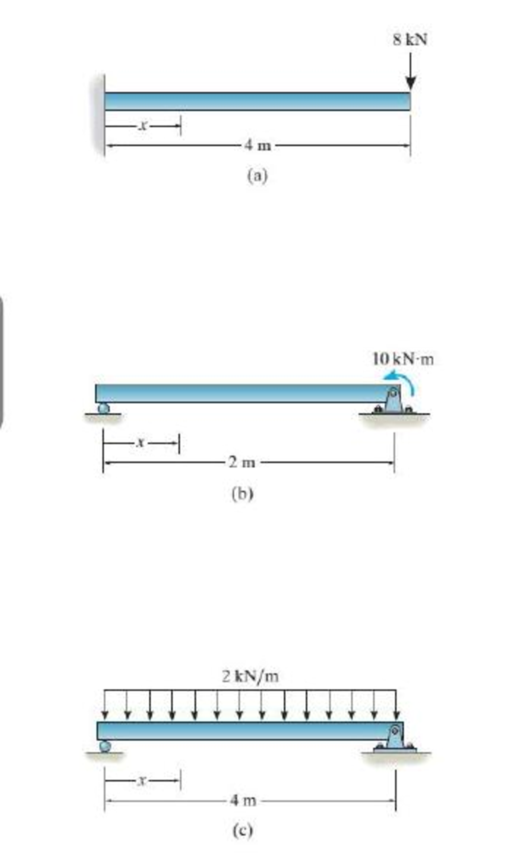
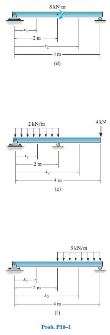
Chapter 16.2, Problem 1PP
In each ease, determine the internal bending moment as a function of x, and state the necessary boundary and/or continuity conditions used to determine the elastic curve for the beam.
Expert Solution & Answer
Want to see the full answer?
Check out a sample textbook solution
Students have asked these similar questions
The cantilever beam carries a uniformly varying load as shown. In addition, a 1000 lb-upwardvertical load acts at the free end of the beam. Derive the shear force and bending momentequations and draw the shear force and bending moment diagrams. Neglect the weight of thebeam
Determine the shear force, V and its bending moment, M. kindly provide the SFD and BMD
Draw the shear force diagram for the following beam
Chapter 16 Solutions
EBK STATICS AND MECHANICS OF MATERIALS
Ch. 16.2 - In each ease, determine the internal bending...Ch. 16.2 - Prob. 1FPCh. 16.2 - Determine the slope and deflection of end A of the...Ch. 16.2 - Prob. 3FPCh. 16.2 - Prob. 4FPCh. 16.2 - Determine the maximum deflection of the simply...Ch. 16.2 - Prob. 6FPCh. 16.2 - An L2 steel strap having a thickness of 0.125 in....Ch. 16.2 - The L2 steel blade of the band saw wraps around...Ch. 16.2 - A picture is taken of a man performing a pole...
Ch. 16.2 - Determine the equation of the elastic curve for...Ch. 16.2 - Determine the deflection of end C of the...Ch. 16.2 - Prob. 6PCh. 16.2 - The A-36 steel beam has a depth of 10 in. and is...Ch. 16.2 - Prob. 8PCh. 16.2 - Determine the equations of the elastic curve for...Ch. 16.2 - Determine the equations of the elastic curve using...Ch. 16.2 - Determine the equations of the elastic curve using...Ch. 16.2 - Prob. 12PCh. 16.2 - Determine the maximum deflection of the beam and...Ch. 16.2 - The simply supported shaft has a moment of inertia...Ch. 16.2 - A torque wrench is used to tighten the nut on a...Ch. 16.2 - The pipe can be assumed roller supported at its...Ch. 16.2 - Determine the equations of the elastic curve for...Ch. 16.2 - The bar is supported by a roller constraint at B,...Ch. 16.2 - The bar is supported by a roller constraint at B,...Ch. 16.2 - Determine the equations of the elastic curve using...Ch. 16.2 - Prob. 21PCh. 16.2 - Determine the elastic curve for the cantilevered...Ch. 16.2 - Prob. 23PCh. 16.2 - Prob. 24PCh. 16.2 - The floor beam of the airplane is subjected to the...Ch. 16.2 - Determine the maximum deflection of the simply...Ch. 16.2 - The beam is made of a material having a specific...Ch. 16.2 - Determine the slope at end B and the maximum...Ch. 16.2 - Prob. 29PCh. 16.2 - Determine the equations of the elastic curve using...Ch. 16.3 - The shaft is supported at A by a journal bearing...Ch. 16.3 - The shaft supports the two pulley loads shown....Ch. 16.3 - Prob. 33PCh. 16.3 - Prob. 34PCh. 16.3 - The beam is subjected to the load shown. Determine...Ch. 16.3 - Prob. 36PCh. 16.3 - Determine the equation of the elastic curve and...Ch. 16.3 - Prob. 38PCh. 16.3 - Prob. 39PCh. 16.3 - Determine the slope at A and the deflection of end...Ch. 16.3 - Determine the maximum deflection in region AB of...Ch. 16.3 - Prob. 42PCh. 16.3 - Prob. 43PCh. 16.3 - Prob. 44PCh. 16.4 - The W10 15 cantilevered beam is made of A-36...Ch. 16.4 - The W10 15 cantilevered beam is made of A-36...Ch. 16.4 - The W14 43 simply supported beam is made of A992...Ch. 16.4 - The W14 43 simply supported beam is made of A992...Ch. 16.4 - The W14 43 simply supported beam is made of A-36...Ch. 16.4 - The W14 43 simply supported beam is made of A-36...Ch. 16.4 - The W8 48 cantilevered beam is made of A-36 steel...Ch. 16.4 - The beam supports the loading shown. Code...Ch. 16.4 - Prob. 53PCh. 16.4 - The W8 48 cantilevered beam is made of A-36 steel...Ch. 16.4 - Prob. 55PCh. 16.4 - Prob. 56PCh. 16.4 - Prob. 57PCh. 16.4 - The assembly consists of a cantilevered beam CB...Ch. 16.4 - Prob. 59PCh. 16.4 - Prob. 60PCh. 16.5 - Determine the reactions at the fixed support A and...Ch. 16.5 - Prob. 8FPCh. 16.5 - Determine the reactions at the fixed support A and...Ch. 16.5 - Prob. 10FPCh. 16.5 - Prob. 11FPCh. 16.5 - Prob. 12FPCh. 16.5 - Prob. 61PCh. 16.5 - Determine the reactions at the supports, then draw...Ch. 16.5 - Determine the reactions at the supports, then draw...Ch. 16.5 - Prob. 64PCh. 16.5 - The beam is used to support the 20-kip load....Ch. 16.5 - Prob. 66PCh. 16.5 - Determine the reactions at the supports A and B....Ch. 16.5 - Before the uniform distributed load is applied to...Ch. 16.5 - Prob. 69PCh. 16.5 - Prob. 70PCh. 16.5 - The beam is supported by the bolted supports at...Ch. 16.5 - Prob. 72PCh. 16.5 - Prob. 73PCh. 16 - Prob. 1RPCh. 16 - Draw the bending-moment diagram for the shaft and...Ch. 16 - Prob. 3RPCh. 16 - Determine the equations of the elastic curve for...Ch. 16 - Determine the maximum deflection between the...Ch. 16 - Prob. 6RPCh. 16 - The framework consists of two A-36 steel...Ch. 16 - Prob. 8RPCh. 16 - Using the method of superposition, determine the...
Knowledge Booster


Learn more about
Need a deep-dive on the concept behind this application? Look no further. Learn more about this topic, mechanical-engineering and related others by exploring similar questions and additional content below.Similar questions
- The beam is supported by a roller at B and a pin at C and is subjected to the distributed load shown with intensity w = 140 N/m. The maximum positive and negative internal bending moments are critical factors in the design of the beam material and geometry. On your written homework draw a full free body diagram of the beam including all reaction forces. Directly under the free body diagram, draw a shear and bending moment diagram. Using your diagranms, determine the largest positive and negative internal bending moments that occur in the beam and the points along the length where each occurs. Take r = 0 to be at point A at the left edge of the beam. В -b- Values for dimensions on the figure are given in the following table. Note the figure may not be to scale. Variable Value a 2.60 m 3.77 m The maximum negative internal bending moment is N-m and occurs at a = m to the right of A. The maximum positive internal bending moment is N-m and occurs at x = m to the right of A.arrow_forwardSmooth journal bearings at A and B that only exert vertical reactions on the shaft as shown below support the shaft. Based on the loading and support conditions shown, address the following: (a) Sketch the shear and moment diagrams using the graphical method - label all significant conditions. (b) If d = 90 mm, determine the absolute maximum bending stress in the beam, and sketch the stress distribution acting over the cross section. A 3 m 12 kN/m B 1.5 marrow_forwardThe cantilevered beam has a rectangular crosssectional area A, a moment of inertia I, and a modulus of elasticity E. If a load P acts at point B as shown, determine the displacement at B in the direction of P, accounting for bending, axial force, and shear.arrow_forward
- Determine the reactions and draw the shear and bending moment diagrams for the beams shown, using the method of consistent deformations. Select the reaction of the Roller support to be the redundantarrow_forwardDetermine the internal normal force and shear force, and the bending moment in the beam at points C and D. Assume the support at B is a roller. Point C is located just to the right of the 8-kip load.arrow_forwardUse n=14. Determine the external reactions at the roller and pin supporting the above beam. Determine the internal reactions (shear and bending moment) at points B, D and F using the method of sections. Determine the shear and moment equations for the beam section under the triangular load, and the shear and moment equations for the beam section under the rectangular load. Draw the shear and bending moment diagrams using the area method showing the differential relations that exist between the load, shear and moment at each section of the beam. Label the diagrams properly indicating where the shear and moment values are positive and negative. Also show on the diagram all the maximum and minimum shear and moment values. arrow_forward
- Produce the Shear Force and Bending Moment Diagram.where Roll No=11arrow_forwardProduce the Shear Force and Bending Moment Diagram. where Roll No=11arrow_forwardDetermine the bending moment M in the beam at the point located 0.44 m to the right of point B. The ground reactions and shear-force diagram are shown.arrow_forward
- Q1/ A beam of uniform section with rigidly fixed ends which are at the same level has an effective span of 10 m. It carries loads of 30 kN and 50 kN at 3 m and 6 m respectively from the left-hand end. Find the vertical reactions and the fixing moments at each end of the beam. Determine the bending moments at the two points of loading.arrow_forwardDetermine the maximum absolute values of the shear and bending moment.arrow_forwardThe simply supported beam is subjected to the force F = 700 N and the uniform distributed load with intensity w = 150 N/m. Draw the shear force and bending moment diagrams (in your homework documentation) and determine the equations for V(r) and M(x). Take a = 0 at point A. 19 F a Values for dimensions on the figure are given in the following table. Note the figure may not be to scale. Variable Value a 5.2 m 2.6 m 3.12 m Support Reactions The reaction at A is N. The reaction at D is N. Shear Force and Bending Moment Equations In section AB: V(x)= N and M(x)= N-m. In section BC: v(x)- N and M(x)= N-m. In section CD: V(x)- N and M(x)= N-m. Aarrow_forward
arrow_back_ios
SEE MORE QUESTIONS
arrow_forward_ios
Recommended textbooks for you
 Elements Of ElectromagneticsMechanical EngineeringISBN:9780190698614Author:Sadiku, Matthew N. O.Publisher:Oxford University Press
 Mechanics of Materials (10th Edition)Mechanical EngineeringISBN:9780134319650Author:Russell C. HibbelerPublisher:PEARSON
 Thermodynamics: An Engineering ApproachMechanical EngineeringISBN:9781259822674Author:Yunus A. Cengel Dr., Michael A. BolesPublisher:McGraw-Hill Education
 Control Systems EngineeringMechanical EngineeringISBN:9781118170519Author:Norman S. NisePublisher:WILEY
 Mechanics of Materials (MindTap Course List)Mechanical EngineeringISBN:9781337093347Author:Barry J. Goodno, James M. GerePublisher:Cengage Learning
 Engineering Mechanics: StaticsMechanical EngineeringISBN:9781118807330Author:James L. Meriam, L. G. Kraige, J. N. BoltonPublisher:WILEY
Elements Of Electromagnetics
Mechanical Engineering
ISBN:9780190698614
Author:Sadiku, Matthew N. O.
Publisher:Oxford University Press
Mechanics of Materials (10th Edition)
Mechanical Engineering
ISBN:9780134319650
Author:Russell C. Hibbeler
Publisher:PEARSON
Thermodynamics: An Engineering Approach
Mechanical Engineering
ISBN:9781259822674
Author:Yunus A. Cengel Dr., Michael A. Boles
Publisher:McGraw-Hill Education
Control Systems Engineering
Mechanical Engineering
ISBN:9781118170519
Author:Norman S. Nise
Publisher:WILEY
Mechanics of Materials (MindTap Course List)
Mechanical Engineering
ISBN:9781337093347
Author:Barry J. Goodno, James M. Gere
Publisher:Cengage Learning
Engineering Mechanics: Statics
Mechanical Engineering
ISBN:9781118807330
Author:James L. Meriam, L. G. Kraige, J. N. Bolton
Publisher:WILEY
Mechanics of Materials Lecture: Beam Design; Author: UWMC Engineering;https://www.youtube.com/watch?v=-wVs5pvQPm4;License: Standard Youtube License