
Statics and Mechanics of Materials, Student Value Edition (5th Edition)
5th Edition
ISBN: 9780134382890
Author: Russell C. Hibbeler
Publisher: PEARSON
expand_more
expand_more
format_list_bulleted
Videos
Textbook Question
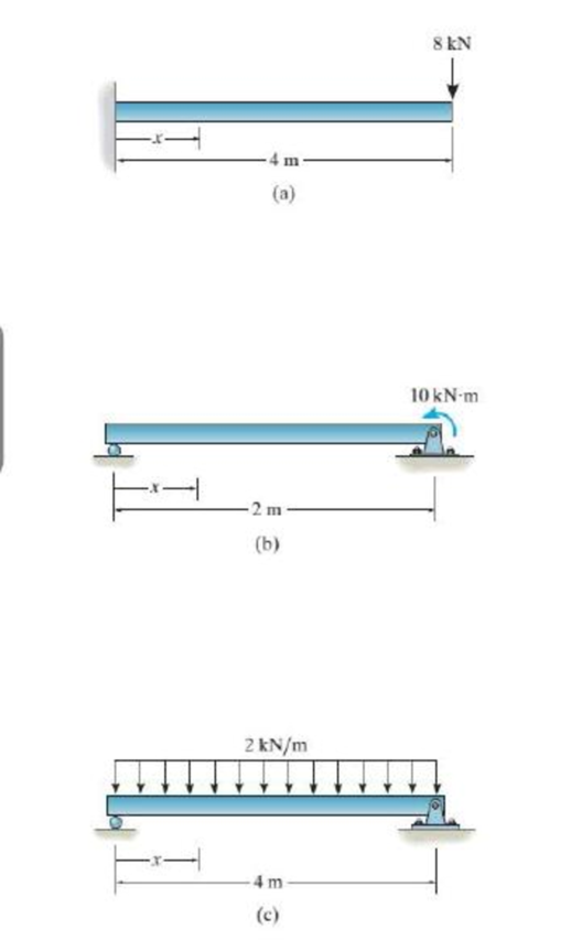
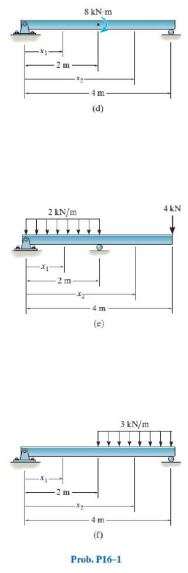
Chapter 16.2, Problem 1PP
In each ease, determine the internal bending moment as a function of x, and state the necessary boundary and/or continuity conditions used to determine the elastic curve for the beam.
Expert Solution & Answer
Want to see the full answer?
Check out a sample textbook solution
Students have asked these similar questions
The beam is supported by a roller at B and a pin at C and is subjected to the distributed load shown with
intensity w = 140 N/m. The maximum positive and negative internal bending moments are critical factors
in the design of the beam material and geometry.
On your written homework draw a full free body diagram of the beam including all reaction forces. Directly
under the free body diagram, draw a shear and bending moment diagram.
Using your diagranms, determine the largest positive and negative internal bending moments that occur in
the beam and the points along the length where each occurs. Take r = 0 to be at point A at the left edge
of the beam.
В
-b-
Values for dimensions on the figure are given in the following table. Note the figure may not be to scale.
Variable Value
a
2.60 m
3.77 m
The maximum negative internal bending moment is
N-m
and occurs at a =
m to the right of A.
The maximum positive internal bending moment is
N-m
and occurs at x =
m to the right of A.
The cantilevered beam has a rectangular cross-sectional area A, a moment of inertia I, and a modulus of elasticity E. If a load P acts at point B as shown, determine the displacement at B in the direction of P, accounting for bending, axial force, and shear.
Q1/ A beam of uniform section with rigidly fixed ends which are at the same level has an effective span of 10 m. It carries loads of 30 kN and 50 kN at 3 m and 6 m respectively from the left-hand end. Find the vertical reactions and the fixing moments at each end of the beam. Determine the bending moments at the two points of loading.
Chapter 16 Solutions
Statics and Mechanics of Materials, Student Value Edition (5th Edition)
Ch. 16.2 - In each ease, determine the internal bending...Ch. 16.2 - Prob. 1FPCh. 16.2 - Determine the slope and deflection of end A of the...Ch. 16.2 - Prob. 3FPCh. 16.2 - Prob. 4FPCh. 16.2 - Determine the maximum deflection of the simply...Ch. 16.2 - Prob. 6FPCh. 16.2 - An L2 steel strap having a thickness of 0.125 in....Ch. 16.2 - The L2 steel blade of the band saw wraps around...Ch. 16.2 - A picture is taken of a man performing a pole...
Ch. 16.2 - Determine the equation of the elastic curve for...Ch. 16.2 - Determine the deflection of end C of the...Ch. 16.2 - Prob. 6PCh. 16.2 - The A-36 steel beam has a depth of 10 in. and is...Ch. 16.2 - Prob. 8PCh. 16.2 - Determine the equations of the elastic curve for...Ch. 16.2 - Determine the equations of the elastic curve using...Ch. 16.2 - Determine the equations of the elastic curve using...Ch. 16.2 - Prob. 12PCh. 16.2 - Determine the maximum deflection of the beam and...Ch. 16.2 - The simply supported shaft has a moment of inertia...Ch. 16.2 - A torque wrench is used to tighten the nut on a...Ch. 16.2 - The pipe can be assumed roller supported at its...Ch. 16.2 - Determine the equations of the elastic curve for...Ch. 16.2 - The bar is supported by a roller constraint at B,...Ch. 16.2 - The bar is supported by a roller constraint at B,...Ch. 16.2 - Determine the equations of the elastic curve using...Ch. 16.2 - Prob. 21PCh. 16.2 - Determine the elastic curve for the cantilevered...Ch. 16.2 - Prob. 23PCh. 16.2 - Prob. 24PCh. 16.2 - The floor beam of the airplane is subjected to the...Ch. 16.2 - Determine the maximum deflection of the simply...Ch. 16.2 - The beam is made of a material having a specific...Ch. 16.2 - Determine the slope at end B and the maximum...Ch. 16.2 - Prob. 29PCh. 16.2 - Determine the equations of the elastic curve using...Ch. 16.3 - The shaft is supported at A by a journal bearing...Ch. 16.3 - The shaft supports the two pulley loads shown....Ch. 16.3 - Prob. 33PCh. 16.3 - Prob. 34PCh. 16.3 - The beam is subjected to the load shown. Determine...Ch. 16.3 - Prob. 36PCh. 16.3 - Determine the equation of the elastic curve and...Ch. 16.3 - Prob. 38PCh. 16.3 - Prob. 39PCh. 16.3 - Determine the slope at A and the deflection of end...Ch. 16.3 - Determine the maximum deflection in region AB of...Ch. 16.3 - Prob. 42PCh. 16.3 - Prob. 43PCh. 16.3 - Prob. 44PCh. 16.4 - The W10 15 cantilevered beam is made of A-36...Ch. 16.4 - The W10 15 cantilevered beam is made of A-36...Ch. 16.4 - The W14 43 simply supported beam is made of A992...Ch. 16.4 - The W14 43 simply supported beam is made of A992...Ch. 16.4 - The W14 43 simply supported beam is made of A-36...Ch. 16.4 - The W14 43 simply supported beam is made of A-36...Ch. 16.4 - The W8 48 cantilevered beam is made of A-36 steel...Ch. 16.4 - The beam supports the loading shown. Code...Ch. 16.4 - Prob. 53PCh. 16.4 - The W8 48 cantilevered beam is made of A-36 steel...Ch. 16.4 - Prob. 55PCh. 16.4 - Prob. 56PCh. 16.4 - Prob. 57PCh. 16.4 - The assembly consists of a cantilevered beam CB...Ch. 16.4 - Prob. 59PCh. 16.4 - Prob. 60PCh. 16.5 - Determine the reactions at the fixed support A and...Ch. 16.5 - Prob. 8FPCh. 16.5 - Determine the reactions at the fixed support A and...Ch. 16.5 - Prob. 10FPCh. 16.5 - Prob. 11FPCh. 16.5 - Prob. 12FPCh. 16.5 - Prob. 61PCh. 16.5 - Determine the reactions at the supports, then draw...Ch. 16.5 - Determine the reactions at the supports, then draw...Ch. 16.5 - Prob. 64PCh. 16.5 - The beam is used to support the 20-kip load....Ch. 16.5 - Prob. 66PCh. 16.5 - Determine the reactions at the supports A and B....Ch. 16.5 - Before the uniform distributed load is applied to...Ch. 16.5 - Prob. 69PCh. 16.5 - Prob. 70PCh. 16.5 - The beam is supported by the bolted supports at...Ch. 16.5 - Prob. 72PCh. 16.5 - Prob. 73PCh. 16 - Prob. 1RPCh. 16 - Draw the bending-moment diagram for the shaft and...Ch. 16 - Prob. 3RPCh. 16 - Determine the equations of the elastic curve for...Ch. 16 - Determine the maximum deflection between the...Ch. 16 - Prob. 6RPCh. 16 - The framework consists of two A-36 steel...Ch. 16 - Prob. 8RPCh. 16 - Using the method of superposition, determine the...
Knowledge Booster


Learn more about
Need a deep-dive on the concept behind this application? Look no further. Learn more about this topic, mechanical-engineering and related others by exploring similar questions and additional content below.Similar questions
- The beam is supported by a roller at B and a pin at C and is subjected to the distributed load shown with intensity w = 180 N/m. The maximum positive and negative internal bending moments are critical factors in the design of the beam material and geometry. Determine the largest positive and negative internal bending moments that occur in the beam and the points along the length where each occurs. Take x = 0 to be at point A at the left edge of the beam. %3D cc BY NC SA 2016 Eric Davishahl B -b- Values for dimensions on the figure are given in the following table. Note the figure may not be to scale. Variable Value a 3.20 m b 3.68 m The maximum negative internal bending moment is N-m and occurs at x = m to the right of A. The maximum positive internal bending moment is N-m and occurs at x = m to the right of A.arrow_forwardDetermine the internal normal force at point C, if F = 48 kN . Determine the shear force at point C Determine the bending moment at point Carrow_forwardConstruct the shear force and bending moment diagrams for the beam shown by the area method. From the diagrams, determine the maximum shear force and maximum bending moment. Neglect the weight of the beam. (Show complete calculation and step by step process. Show free body diagram)arrow_forward
- . show step-by-step solution and schematic diagram if possible.arrow_forwardThe cantilevered beam has a rectangular crosssectional area A, a moment of inertia I, and a modulus of elasticity E. If a load P acts at point B as shown, determine the displacement at B in the direction of P, accounting for bending, axial force, and shear.arrow_forwardQuestion 3: The beam is subjected to the uniform distributed load shown. Draw the shear and moment diagrams for the beam. Take: A = C kN/m 2 B = 1.5 m C = kN /m B В m A m 1m Solution: Equation of Equilibrium: C(A+1) kN C kNlm 0.5(A+1) m Ax 4 AM Im Fec A meter (a) (b) 2MA = 0; Fec (3 /5)A – 0.5C(A +1)° = 0 F, = 0; A, + Fec (3/5)- C(A +1) = 0 kN A, = kN kN V, = M(KN.M) m X2 v3 M1 V2 kN vl V, = kN x2 x2 м, M3 M, = v2 (C) (d)arrow_forward
- determine the support reactions for the beam on the left if w= 150N/m and L= 4m. Do Not ShortCut the Static, V(x), and M(x) Analysesarrow_forwardThe beam ABis attached to the wall in the zz plane by a fixed support at A. A force of F = (- 156i + 58.0j + 350k) N is applied to the end of the beam at B. The weight of the beam can be modeled with a uniform distributed load of intensity w = 65.0 N/m acting in the negative z direction along its entire length. Find the support reactions at Á. F B y а Values for dimensions on the figure are given in the following table. Note the figure may not be to scale. Variable Value 5.80 m 5.00 m 3.80 m A = i+ j- k) N MA = k) N-marrow_forwardDraw the shear diagram for the beam. Follow the sign convention. Draw the moment diagram for the beam. Follow the sign convention.arrow_forward
- Nonearrow_forwardFor the beam shown, determine in terms of W, L, E, and I: The equation of the elastic curve The rotations at points A and B Deflection of point C The maximum deflection of the beam Check the results of parts b and c using the Area Moment Methodarrow_forward4o. kN/m nm + 'yo 40 Determine the reactions at A and B for the beam subjected to the uniform load distribution mm B Draw the shear-force and bending-moment diagrams for the loaded beam and determine the maximum moment M and its location x from the left endarrow_forward
arrow_back_ios
SEE MORE QUESTIONS
arrow_forward_ios
Recommended textbooks for you
 Elements Of ElectromagneticsMechanical EngineeringISBN:9780190698614Author:Sadiku, Matthew N. O.Publisher:Oxford University Press
 Mechanics of Materials (10th Edition)Mechanical EngineeringISBN:9780134319650Author:Russell C. HibbelerPublisher:PEARSON
 Thermodynamics: An Engineering ApproachMechanical EngineeringISBN:9781259822674Author:Yunus A. Cengel Dr., Michael A. BolesPublisher:McGraw-Hill Education
 Control Systems EngineeringMechanical EngineeringISBN:9781118170519Author:Norman S. NisePublisher:WILEY
 Mechanics of Materials (MindTap Course List)Mechanical EngineeringISBN:9781337093347Author:Barry J. Goodno, James M. GerePublisher:Cengage Learning
 Engineering Mechanics: StaticsMechanical EngineeringISBN:9781118807330Author:James L. Meriam, L. G. Kraige, J. N. BoltonPublisher:WILEY
Elements Of Electromagnetics
Mechanical Engineering
ISBN:9780190698614
Author:Sadiku, Matthew N. O.
Publisher:Oxford University Press
Mechanics of Materials (10th Edition)
Mechanical Engineering
ISBN:9780134319650
Author:Russell C. Hibbeler
Publisher:PEARSON
Thermodynamics: An Engineering Approach
Mechanical Engineering
ISBN:9781259822674
Author:Yunus A. Cengel Dr., Michael A. Boles
Publisher:McGraw-Hill Education
Control Systems Engineering
Mechanical Engineering
ISBN:9781118170519
Author:Norman S. Nise
Publisher:WILEY
Mechanics of Materials (MindTap Course List)
Mechanical Engineering
ISBN:9781337093347
Author:Barry J. Goodno, James M. Gere
Publisher:Cengage Learning
Engineering Mechanics: Statics
Mechanical Engineering
ISBN:9781118807330
Author:James L. Meriam, L. G. Kraige, J. N. Bolton
Publisher:WILEY
Mechanics of Materials Lecture: Beam Design; Author: UWMC Engineering;https://www.youtube.com/watch?v=-wVs5pvQPm4;License: Standard Youtube License