
Statics and Mechanics of Materials, Student Value Edition (5th Edition)
5th Edition
ISBN: 9780134382890
Author: Russell C. Hibbeler
Publisher: PEARSON
expand_more
expand_more
format_list_bulleted
Videos
Textbook Question
Chapter 16.5, Problem 68P
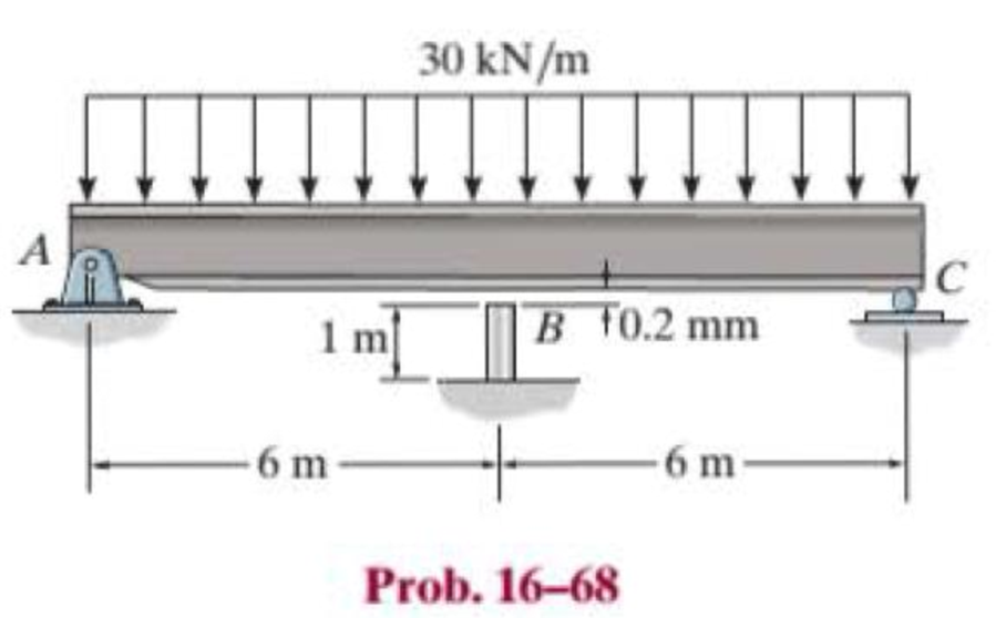
Before the uniform distributed load is applied to the beam, there is a small gap of 0.2 mm between the beam and the post at B. Determine the support reactions at A, B, and C. The post at B has a diameter of 40 mm, and the moment of inertia of the beam is I = 875(106) mm4. The post and the beam are made of material having a modulus of elasticity of E = 200 GPa.
Expert Solution & Answer
Want to see the full answer?
Check out a sample textbook solution
Students have asked these similar questions
The beam is supported by a pin at A, a roller at B, and a post having a diameter of 50 mm at C. Determine the support reactions at A, B, and C. The post and the beam are made of the same material having a modulus of elasticity E = 200 GPa, and the beam has a constant moment of inertia I = 255(106) mm4.
The horizontal beam is assumed to be rigid and
supports the distributed load shown. Determine the vertical
reactions at the supports. Each support consists of a wooden
post having a diameter of 120 mm and an unloaded
(original) length of 1.40 m. Take E = 12 GPa.
The horizontal beam is assumed to be rigid and
supports the distributed load shown. Determine the angle
of tilt of the beam after the load is applied. Each support
consists of a wooden post having a diameter of 120 mm and
an unloaded (original) length of 1.40 m. Take Ew = 12 GPa.
18 kN/m
A
1.40 m
2 m
+1m-
1. Determine the horizontal and vertical components of the reaction at the supports. Neglect the thickness of the beam.
See the attached image to solve the problem:
Chapter 16 Solutions
Statics and Mechanics of Materials, Student Value Edition (5th Edition)
Ch. 16.2 - In each ease, determine the internal bending...Ch. 16.2 - Prob. 1FPCh. 16.2 - Determine the slope and deflection of end A of the...Ch. 16.2 - Prob. 3FPCh. 16.2 - Prob. 4FPCh. 16.2 - Determine the maximum deflection of the simply...Ch. 16.2 - Prob. 6FPCh. 16.2 - An L2 steel strap having a thickness of 0.125 in....Ch. 16.2 - The L2 steel blade of the band saw wraps around...Ch. 16.2 - A picture is taken of a man performing a pole...
Ch. 16.2 - Determine the equation of the elastic curve for...Ch. 16.2 - Determine the deflection of end C of the...Ch. 16.2 - Prob. 6PCh. 16.2 - The A-36 steel beam has a depth of 10 in. and is...Ch. 16.2 - Prob. 8PCh. 16.2 - Determine the equations of the elastic curve for...Ch. 16.2 - Determine the equations of the elastic curve using...Ch. 16.2 - Determine the equations of the elastic curve using...Ch. 16.2 - Prob. 12PCh. 16.2 - Determine the maximum deflection of the beam and...Ch. 16.2 - The simply supported shaft has a moment of inertia...Ch. 16.2 - A torque wrench is used to tighten the nut on a...Ch. 16.2 - The pipe can be assumed roller supported at its...Ch. 16.2 - Determine the equations of the elastic curve for...Ch. 16.2 - The bar is supported by a roller constraint at B,...Ch. 16.2 - The bar is supported by a roller constraint at B,...Ch. 16.2 - Determine the equations of the elastic curve using...Ch. 16.2 - Prob. 21PCh. 16.2 - Determine the elastic curve for the cantilevered...Ch. 16.2 - Prob. 23PCh. 16.2 - Prob. 24PCh. 16.2 - The floor beam of the airplane is subjected to the...Ch. 16.2 - Determine the maximum deflection of the simply...Ch. 16.2 - The beam is made of a material having a specific...Ch. 16.2 - Determine the slope at end B and the maximum...Ch. 16.2 - Prob. 29PCh. 16.2 - Determine the equations of the elastic curve using...Ch. 16.3 - The shaft is supported at A by a journal bearing...Ch. 16.3 - The shaft supports the two pulley loads shown....Ch. 16.3 - Prob. 33PCh. 16.3 - Prob. 34PCh. 16.3 - The beam is subjected to the load shown. Determine...Ch. 16.3 - Prob. 36PCh. 16.3 - Determine the equation of the elastic curve and...Ch. 16.3 - Prob. 38PCh. 16.3 - Prob. 39PCh. 16.3 - Determine the slope at A and the deflection of end...Ch. 16.3 - Determine the maximum deflection in region AB of...Ch. 16.3 - Prob. 42PCh. 16.3 - Prob. 43PCh. 16.3 - Prob. 44PCh. 16.4 - The W10 15 cantilevered beam is made of A-36...Ch. 16.4 - The W10 15 cantilevered beam is made of A-36...Ch. 16.4 - The W14 43 simply supported beam is made of A992...Ch. 16.4 - The W14 43 simply supported beam is made of A992...Ch. 16.4 - The W14 43 simply supported beam is made of A-36...Ch. 16.4 - The W14 43 simply supported beam is made of A-36...Ch. 16.4 - The W8 48 cantilevered beam is made of A-36 steel...Ch. 16.4 - The beam supports the loading shown. Code...Ch. 16.4 - Prob. 53PCh. 16.4 - The W8 48 cantilevered beam is made of A-36 steel...Ch. 16.4 - Prob. 55PCh. 16.4 - Prob. 56PCh. 16.4 - Prob. 57PCh. 16.4 - The assembly consists of a cantilevered beam CB...Ch. 16.4 - Prob. 59PCh. 16.4 - Prob. 60PCh. 16.5 - Determine the reactions at the fixed support A and...Ch. 16.5 - Prob. 8FPCh. 16.5 - Determine the reactions at the fixed support A and...Ch. 16.5 - Prob. 10FPCh. 16.5 - Prob. 11FPCh. 16.5 - Prob. 12FPCh. 16.5 - Prob. 61PCh. 16.5 - Determine the reactions at the supports, then draw...Ch. 16.5 - Determine the reactions at the supports, then draw...Ch. 16.5 - Prob. 64PCh. 16.5 - The beam is used to support the 20-kip load....Ch. 16.5 - Prob. 66PCh. 16.5 - Determine the reactions at the supports A and B....Ch. 16.5 - Before the uniform distributed load is applied to...Ch. 16.5 - Prob. 69PCh. 16.5 - Prob. 70PCh. 16.5 - The beam is supported by the bolted supports at...Ch. 16.5 - Prob. 72PCh. 16.5 - Prob. 73PCh. 16 - Prob. 1RPCh. 16 - Draw the bending-moment diagram for the shaft and...Ch. 16 - Prob. 3RPCh. 16 - Determine the equations of the elastic curve for...Ch. 16 - Determine the maximum deflection between the...Ch. 16 - Prob. 6RPCh. 16 - The framework consists of two A-36 steel...Ch. 16 - Prob. 8RPCh. 16 - Using the method of superposition, determine the...
Knowledge Booster


Learn more about
Need a deep-dive on the concept behind this application? Look no further. Learn more about this topic, mechanical-engineering and related others by exploring similar questions and additional content below.Similar questions
- Provide the correct exponents and distances to make the singularity function given valid for the beam shown. V₁ = 8 kN, V2 = 7 kN, V3 = 200 mm, and V4 = 1100 mm. Determine the reaction forces at the supports. ATATV3 -V3- (mm) O The singularity functions are q = R₁(x)ª − v₁(x − P)ª − v₂(x − Q)¹ + R₂(x − R)ª V = R₁ – v₁(x – D)³ − v2(x − E)³ + R2(x – F)³ M = R₁x – v₁(x – G)ª − v₂(x − H)C + R₂(x − 1)C From the given singularity functions the exponents aro (1) (2)arrow_forwardThe bent bar is supported by smooth journal bearings at A, B and C and is subjected to couple moment of 200 N.m. Determine the support reaction at each of the smooth journal bearings. 200 N.m /0.4 m/ B 0.7 m 0.6 m Figure 2arrow_forwardThe beam ABis attached to the wall in the zz plane by a fixed support at A. A force of F = (- 156i + 58.0j + 350k) N is applied to the end of the beam at B. The weight of the beam can be modeled with a uniform distributed load of intensity w = 65.0 N/m acting in the negative z direction along its entire length. Find the support reactions at Á. F B y а Values for dimensions on the figure are given in the following table. Note the figure may not be to scale. Variable Value 5.80 m 5.00 m 3.80 m A = i+ j- k) N MA = k) N-marrow_forward
- Determine the reactions at A and B for the beam subjected to the couples and distributed load. At x = 0, the distributed load is increasing at the rate of 9 lb/ft per foot. Assume a = 5 ft, b = 20 ft, w₁ = 150 lb/ft, w₂ = 420 lb/ft, M₁ = 2630 lb-ft, M₂ = 1640 lb-ft. M₁ W | w = ko+k₁x + k₂x² potiu ·a+ b B W₂ M₂ -Xarrow_forwardBefore the uniform distributed load is applied to the beam, there is a small gap of 0.2 mm between the beam and the post at B. Determine the support reactions at A, B, and C. The post at B has a diameter of 40 mm, and themoment of inertia of the beam is I = 875(106) mm4. The post and the beam are made of material having a modulus of elasticity of E = 200 GPa.arrow_forwardProvide the correct exponents and distances to make the singularity function given valid for the beam shown. VI = 8 kN, V2 = 8 kN, V3 = 200 mm, and V4 = 1100 mm. Determine the reaction forces at the supports. A v3 V37 (m) o The singularity functions are q = R1(x)ª – v1( – P)ª – v2(x – Q)ª + R2(x – R)ª - 2 - V = R1 – v1(x – D)B – v2(x – E)B + R2(x – F)® (1) M = R1x – v1(x – G)° – v2(x – H)° + R2(x – (2) From the given singularity functions, the exponents are A = B = C= The distances are P= mm Q = mm R= mm D= mm E= mm F= mm G= mm H= mm mm Reactions force R = kN and reaction force R2 = kNarrow_forward
- If the beam shown is supported by the fixed wall at B and the rod AC. if the rod has a cross sectional area = 10 x10-4 m2 and is made of the same material of the beam if the area moment of inertia of the beam's cross section is 9.7 x 10-° m4 if the distributed load w = 8.5 kN, then, the tension in the rod AC is . ... N 1 m 1 m 2 m Oa. 27.57 Ob.926.32 Oc 6.38 Od. 63518.95arrow_forwardDetermine the support reaction of the roller at point B given the following loads: = 232 N/m C D = 24 N/m 5m 4m Darrow_forwardDetermine the vertical reaction (A y - kN) and the reactive moment (M A - kN·m) at the support at A considering thestock values: M = 10·a + 30·b + 20·c + 200 {kN·m}, q = 20·(a + b) + 10·c + 100 {kN/m} and F = 30· (a + b+ c) + 50 {kN}. The beams AB and BC of the beam are interconnected by a smooth pin at B. Assume minimum accuracyof 6 significant figures. (a = 7; b=1 ; c=1) Ay= MA=arrow_forward
- -4 ft- 5 ft R 4 ft A B (6,0,4) ft Given that the force in cable AB has a magnitude of TAB = 8 lbs and the unit vector in the direction of TAB is UAB=0.4361 -0.873j -0.218k. What is the moment reaction at the fixed support C? C and A have the same y-component. -65.5i -45.8j +52.4k ft-lb -52.41 -36.6j +41.9k ft-lb +52.4i +36.6j -41.9k ft-lb +65.5i +45.8j-52.4k ft-lb +34.91 +24.4j -27.9k ft-lb -34.91 -24.4j +27.9k ft-lbarrow_forwardDetermine the components of reaction at E. Take that P= 5.1 kN and w = 3.6 kN/m (Figure 1) Figure 1 of 1 1.5 m -1.5 marrow_forwardThe beam of negligible weight is supported horizontally by two springs. If the beam is horizontal and the springs are unstretched when the load is removed, determine the angle of tilt of the beam when the load is applied. Take x = 659 N/m, y = 1.5 kN/m, and z = 1.6 kN/m.arrow_forward
arrow_back_ios
SEE MORE QUESTIONS
arrow_forward_ios
Recommended textbooks for you
 Elements Of ElectromagneticsMechanical EngineeringISBN:9780190698614Author:Sadiku, Matthew N. O.Publisher:Oxford University Press
 Mechanics of Materials (10th Edition)Mechanical EngineeringISBN:9780134319650Author:Russell C. HibbelerPublisher:PEARSON
 Thermodynamics: An Engineering ApproachMechanical EngineeringISBN:9781259822674Author:Yunus A. Cengel Dr., Michael A. BolesPublisher:McGraw-Hill Education
 Control Systems EngineeringMechanical EngineeringISBN:9781118170519Author:Norman S. NisePublisher:WILEY
 Mechanics of Materials (MindTap Course List)Mechanical EngineeringISBN:9781337093347Author:Barry J. Goodno, James M. GerePublisher:Cengage Learning
 Engineering Mechanics: StaticsMechanical EngineeringISBN:9781118807330Author:James L. Meriam, L. G. Kraige, J. N. BoltonPublisher:WILEY
Elements Of Electromagnetics
Mechanical Engineering
ISBN:9780190698614
Author:Sadiku, Matthew N. O.
Publisher:Oxford University Press
Mechanics of Materials (10th Edition)
Mechanical Engineering
ISBN:9780134319650
Author:Russell C. Hibbeler
Publisher:PEARSON
Thermodynamics: An Engineering Approach
Mechanical Engineering
ISBN:9781259822674
Author:Yunus A. Cengel Dr., Michael A. Boles
Publisher:McGraw-Hill Education
Control Systems Engineering
Mechanical Engineering
ISBN:9781118170519
Author:Norman S. Nise
Publisher:WILEY
Mechanics of Materials (MindTap Course List)
Mechanical Engineering
ISBN:9781337093347
Author:Barry J. Goodno, James M. Gere
Publisher:Cengage Learning
Engineering Mechanics: Statics
Mechanical Engineering
ISBN:9781118807330
Author:James L. Meriam, L. G. Kraige, J. N. Bolton
Publisher:WILEY
Mechanics of Materials Lecture: Beam Design; Author: UWMC Engineering;https://www.youtube.com/watch?v=-wVs5pvQPm4;License: Standard Youtube License