Fundamentals of Electric Circuits
6th Edition
ISBN: 9781259663918
Author: Alexander
Publisher: MCG
expand_more
expand_more
format_list_bulleted
Videos
Textbook Question
Chapter 16.3, Problem 6PP
The initial energy in the circuit of Fig. 16.17 is zero at t = 0. Assume that vs = 360u(t) V. (a) Find Vo(s) using the Thevenin theorem. (b) Apply the initial- and final-value theorems to find vo(0) and vo(∞). (c) Obtain vo(t).
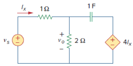
Figure 16.17
Expert Solution & Answer

Trending nowThis is a popular solution!

Students have asked these similar questions
When the unit step function is applied to the system input whose block diagram is given below, the output response takes the value c (0.2) = 0.11 fort = 0.2 s and c (infinity) = 0.333 for t = infinity. What is the time constant of the system? calculate.
Signal and system
The mathematical model of a system is y" (t) + ay'(t) + by(t) = a (t) + ca (t) where a=1, b=2 and c=1.
1) Find zeros and poles of the system.
2) Show them onto the S-Plane (the complex plane)
3) Discuss the BIBO stability of the system.
The block diagram of a time-invariant, linear, continuous-time system is given below. X1(s) and X2(s) are the state variables of the system. U(s) is the input signal of the system, Y(s) is the output signal of the system.
What is the value of parameter E?
Chapter 16 Solutions
Fundamentals of Electric Circuits
Ch. 16.2 - Determine vo(t) in the circuit of Fig. 16.6,...Ch. 16.2 - Prob. 2PPCh. 16.2 - Prob. 3PPCh. 16.3 - For the circuit shown in Fig. 16.12 with the same...Ch. 16.3 - Prob. 5PPCh. 16.3 - The initial energy in the circuit of Fig. 16.17 is...Ch. 16.4 - Prob. 7PPCh. 16.4 - Prob. 8PPCh. 16.4 - Prob. 9PPCh. 16.5 - Obtain the state variable model for the circuit...
Ch. 16.5 - Prob. 11PPCh. 16.5 - Prob. 12PPCh. 16.6 - For what value of is the circuit in Fig. 16.29...Ch. 16.6 - Prob. 14PPCh. 16.6 - Prob. 15PPCh. 16.6 - Synthesize the function Vo(s)Vin=2ss2+6s+10 using...Ch. 16 - Prob. 1RQCh. 16 - The current through an RL series circuit with...Ch. 16 - Prob. 3RQCh. 16 - Prob. 4RQCh. 16 - Prob. 5RQCh. 16 - Prob. 6RQCh. 16 - Prob. 7RQCh. 16 - Prob. 8RQCh. 16 - Prob. 9RQCh. 16 - Prob. 10RQCh. 16 - The current in an RLC circuit is described by...Ch. 16 - The differential equation that describes the...Ch. 16 - Prob. 3PCh. 16 - If R = 20 , L = 0.6 H, what value of C will make...Ch. 16 - The responses of a series RLC circuit are vc(t) =...Ch. 16 - Prob. 6PCh. 16 - Prob. 7PCh. 16 - Prob. 8PCh. 16 - Prob. 9PCh. 16 - The step responses of a series RLC circuit are Vc...Ch. 16 - The step response of a parallel RLC circuit is v =...Ch. 16 - Prob. 12PCh. 16 - Prob. 13PCh. 16 - Prob. 14PCh. 16 - For the circuit in Fig. 16.38. calculate the value...Ch. 16 - The capacitor in the circuit of Fig. 16.39 is...Ch. 16 - If is(t) = 7.5e2t u(t) A in the circuit shown in...Ch. 16 - Find v(t), t 0 in the circuit of Fig. 16.41. Let...Ch. 16 - The switch in Fig. 16.42 moves from position A to...Ch. 16 - Find i(t) for t 0 in the circuit of Fig. 16.43.Ch. 16 - In the circuit of Fig. 16.44, the switch moves...Ch. 16 - Find the voltage across the capacitor as a...Ch. 16 - Obtain v (t) for t 0 in the circuit of Fig....Ch. 16 - The switch in the circuit of Fig. 16.47 has been...Ch. 16 - Calculate v(t) for t 0 in the circuit of Fig....Ch. 16 - Prob. 26PCh. 16 - Find v (t) for t 0 in the circuit in Fig. 16.50.Ch. 16 - For the circuit in Fig. 16.51, find v(t) for t 0.Ch. 16 - Prob. 29PCh. 16 - Find vo(t), for all t 0, in the circuit of Fig....Ch. 16 - Prob. 31PCh. 16 - For the network in Fig. 16.55, solve for i(t) for...Ch. 16 - Using Fig. 16.56, design a problem to help other...Ch. 16 - Prob. 34PCh. 16 - Prob. 35PCh. 16 - Prob. 36PCh. 16 - Prob. 37PCh. 16 - The switch in the circuit of Fig. 16.61 is moved...Ch. 16 - Prob. 39PCh. 16 - Prob. 40PCh. 16 - Prob. 41PCh. 16 - Prob. 42PCh. 16 - Prob. 43PCh. 16 - Prob. 44PCh. 16 - Find v(t) for t 0 in the circuit in Fig. 16.68.Ch. 16 - Prob. 46PCh. 16 - Determine io(t) in the network shown in Fig....Ch. 16 - Prob. 48PCh. 16 - Find i0(t) for t 0 in the circuit in Fig. 16.72....Ch. 16 - Prob. 50PCh. 16 - In the circuit of Fig. 16.74, find i(t) for t 0.Ch. 16 - Prob. 52PCh. 16 - In the circuit of Fig. 16.76, the switch has been...Ch. 16 - Prob. 54PCh. 16 - Prob. 55PCh. 16 - Calculate io(t) for t 0 in the network of Fig....Ch. 16 - Prob. 57PCh. 16 - Prob. 58PCh. 16 - Find vo(t) in the circuit of Fig. 16.82 if vx(0) =...Ch. 16 - Prob. 60PCh. 16 - Prob. 61PCh. 16 - Using Fig. 16.85, design a problem to help other...Ch. 16 - Consider the parallel RLC circuit of Fig. 16.86....Ch. 16 - The switch in Fig. 16.87 moves from position 1 to...Ch. 16 - For the RLC circuit shown in Fig. 16.88, find the...Ch. 16 - For the op amp circuit in Fig. 16.89, find v0(t)...Ch. 16 - Given the op amp circuit in Fig. 16.90, if v1(0+)...Ch. 16 - Prob. 68PCh. 16 - Prob. 69PCh. 16 - Using Fig. 16.93, design a problem to help other...Ch. 16 - Prob. 71PCh. 16 - The transfer function of a system is H(s)=s23s+1...Ch. 16 - Prob. 73PCh. 16 - Design a problem to help other students better...Ch. 16 - Prob. 75PCh. 16 - For the circuit in Fig. 16.95, find H(s) =...Ch. 16 - Obtain the transfer function H(s) = VoVs for the...Ch. 16 - Prob. 78PCh. 16 - For the circuit in Fig. 16.97, find: (a) I1/Vs (b)...Ch. 16 - Refer to the network in Fig. 16.98. Find the...Ch. 16 - Prob. 81PCh. 16 - Prob. 82PCh. 16 - Refer to the RL circuit in Fig. 16.101. Find: (a)...Ch. 16 - A parallel RL circuit has R = 4 and L = 1 H. The...Ch. 16 - Prob. 85PCh. 16 - Prob. 86PCh. 16 - Prob. 87PCh. 16 - Prob. 88PCh. 16 - Develop the state equations for the circuit shown...Ch. 16 - Prob. 90PCh. 16 - Prob. 91PCh. 16 - Prob. 92PCh. 16 - Prob. 93PCh. 16 - Prob. 94PCh. 16 - Prob. 95PCh. 16 - Prob. 96PCh. 16 - A system is formed by cascading two systems as...Ch. 16 - Determine whether the op amp circuit in Fig....Ch. 16 - It is desired realize the transfer function...Ch. 16 - Prob. 100PCh. 16 - Prob. 101PCh. 16 - Synthesize the transfer function...Ch. 16 - Prob. 103CPCh. 16 - Prob. 104CPCh. 16 - Prob. 105CP
Knowledge Booster


Learn more about
Need a deep-dive on the concept behind this application? Look no further. Learn more about this topic, electrical-engineering and related others by exploring similar questions and additional content below.Similar questions
- 40 - When the unit step function is applied to the system input given the block diagram below, the output response takes the value c (infinity) = 3 for t = infinity. So which of the following can be the constants K, a?A) K = 0.05, a = 0.25B) K = 3, a = 1C) K = 0.35, a = 0.55D) K = 1, a = 3E) K = 0.45, a = 0.65arrow_forwardUsing the laplace transformation table, evaluate the following, consideringany other variable other than t as constant: L[rt sin^2(rt)]arrow_forwardFor a continuous time LTI system, the output is given as Y(s)=10(2s+3)/(s2+4s+5). Find out the final value of y(t) using final value theorem.arrow_forward
- Find the convolution of the two sequences x[n] and h[n] given by,h[n] = (1/2)nu[n], x[n] = (1/4)nu[n].arrow_forward25 - When the unit step function is applied to the system input given the block diagram below, the output response takes the value c (0.2) = 0.11 for t = 0.2 s and c (infinity) = 0.333 for t = infinity. What is the time constant of the system? calculate.A) 0.5 sB) 0.33 sC) 2 sD) 0.25 sE) 1 sarrow_forwardUsing the DIFFERENTIAL EQUATION METHODS, Solve for the particular solution of the differential equation as follows:y"'+ 33y"+ 30y'− 64y= 0With the initial conditions as follows: y(0) = 0, y’(0) = -1, y’’’(0) = 33.arrow_forward
- Convolve the x(n) with h(n) * x(n) * and h(n) are given by, x(n) = (1, 2, 3) h(n) = (1, 2, 1)arrow_forwardA)Perform the N=5 point circular convolution of x and h using DFT. B)Perform the N=5 point circular convolution of x and h in time-domain.arrow_forwardIt is expressed as the state equations of a linear time invariant system. dx(t) / d(t) = Ax(t)+Bu(t) Find the state transition matrix Փ(t), the characteristic equation and the eigenvalues of A for the following systemarrow_forward
- It is expressed as the state equations of a linear time invariant system. dx(t) / d(t) = Ax(t)+Bu(t) Find the state transition matrix Փ(t), the characteristic equation and the eigenvalues of A for the following systems:arrow_forwardFind and graph the current i(t) in the RLC circuit of the figure, where R=1 Ω, L= 0,25 H, C=0,2 F, v(t)=377sin(20t) V for (10/π) seconds ≤ t ≤ (25/π) seconds, and v(t) = 0 for 0 ≤ t < (10/π) seconds and (25/π) seconds < t < ∞, considering the initial current and load as null. (Note: Use the Laplace method as they are causal systems)arrow_forwardThe mathematical models of some continuous time systems are given above. x(t) is the input signal of the system, and y(t) is the output signal of the system. Which of the following systems is linear and which is nonlinear?arrow_forward
arrow_back_ios
SEE MORE QUESTIONS
arrow_forward_ios
Recommended textbooks for you
 Introductory Circuit Analysis (13th Edition)Electrical EngineeringISBN:9780133923605Author:Robert L. BoylestadPublisher:PEARSON
 Delmar's Standard Textbook Of ElectricityElectrical EngineeringISBN:9781337900348Author:Stephen L. HermanPublisher:Cengage Learning
 Programmable Logic ControllersElectrical EngineeringISBN:9780073373843Author:Frank D. PetruzellaPublisher:McGraw-Hill Education
 Fundamentals of Electric CircuitsElectrical EngineeringISBN:9780078028229Author:Charles K Alexander, Matthew SadikuPublisher:McGraw-Hill Education
 Electric Circuits. (11th Edition)Electrical EngineeringISBN:9780134746968Author:James W. Nilsson, Susan RiedelPublisher:PEARSON
 Engineering ElectromagneticsElectrical EngineeringISBN:9780078028151Author:Hayt, William H. (william Hart), Jr, BUCK, John A.Publisher:Mcgraw-hill Education,
Introductory Circuit Analysis (13th Edition)
Electrical Engineering
ISBN:9780133923605
Author:Robert L. Boylestad
Publisher:PEARSON
Delmar's Standard Textbook Of Electricity
Electrical Engineering
ISBN:9781337900348
Author:Stephen L. Herman
Publisher:Cengage Learning
Programmable Logic Controllers
Electrical Engineering
ISBN:9780073373843
Author:Frank D. Petruzella
Publisher:McGraw-Hill Education
Fundamentals of Electric Circuits
Electrical Engineering
ISBN:9780078028229
Author:Charles K Alexander, Matthew Sadiku
Publisher:McGraw-Hill Education
Electric Circuits. (11th Edition)
Electrical Engineering
ISBN:9780134746968
Author:James W. Nilsson, Susan Riedel
Publisher:PEARSON
Engineering Electromagnetics
Electrical Engineering
ISBN:9780078028151
Author:Hayt, William H. (william Hart), Jr, BUCK, John A.
Publisher:Mcgraw-hill Education,
Lead and lag compensation using Bode diagrams; Author: John Rossiter;https://www.youtube.com/watch?v=UBE-Tp173vk;License: Standard Youtube License