
Mastering Engineering with Pearson eText -- Standalone Access Card -- for Mechanics of Materials
10th Edition
ISBN: 9780134321288
Author: HIBBELER
Publisher: PEARSON
expand_more
expand_more
format_list_bulleted
Concept explainers
Videos
Textbook Question
Chapter 1.7, Problem 1.93P
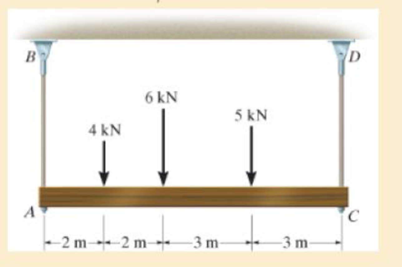
The rods AB and CD are made of steel. Determine their smallest diameter so that they can support the dead loads shown. The beam is assumed to be pin connected at A and C. Use the LRFD method, where the resistance factor for steel in tension is ϕ = 0.9. and the dead load factor is γD = 1.4. The failure stress is σfail = 345 MPa.
Expert Solution & Answer
Want to see the full answer?
Check out a sample textbook solution
Students have asked these similar questions
The rods AB and CD are made of steel. Determine their smallest diameter so that they can support the dead loads shown. The beam is assumed to be pin connected at A and C. Use the LRFD method, where the resistance factorfor steel in tension is f = 0.9, and the dead load factor is gD = 1.4. The failure stress is sfail = 345 MPa.
A steel column is of length 8m and diameter 600 mm with both ends hinged.Determine the crippling load by Euler’s formula. Take 5 E = 2.1x10 N/mm2
The ultimate stress for a hollow steel column which carries an axial load of 1.9MN is 480N/mm if the external diameter of the column is 200mm determine the internal diameter. Take the factor of safety as 4
Chapter 1 Solutions
Mastering Engineering with Pearson eText -- Standalone Access Card -- for Mechanics of Materials
Ch. 1.2 - In each case, explain how to find the resultant...Ch. 1.2 - Determine the resultant internal normal force,...Ch. 1.2 - Determine the resultant internal normal force,...Ch. 1.2 - Determine the resultant internal normal force,...Ch. 1.2 - Determine the resultant internal normal force,...Ch. 1.2 - Determine the resultant internal normal force,...Ch. 1.2 - Determine the resultant internal normal force,...Ch. 1.2 - The shaft is supported by a smooth thrust bearing...Ch. 1.2 - Determine the resultant internal normal and shear...Ch. 1.2 - Determine the resultant internal loadings acting...
Ch. 1.2 - The shaft is supported by a smooth thrust bearing...Ch. 1.2 - Determine the resultant internal loadings acting...Ch. 1.2 - Determine the resultant internal loadings on the...Ch. 1.2 - Determine the resultant internal loadings at cross...Ch. 1.2 - The beam supports the distributed load shown....Ch. 1.2 - The beam supports the distributed load shown....Ch. 1.2 - The boom DF of the jib crane and the column DE...Ch. 1.2 - Determine the resultant internal loadings acting...Ch. 1.2 - Determine the resultant internal loadings acting...Ch. 1.2 - The blade of the hacksaw is subjected to a...Ch. 1.2 - The blade of the hacksaw is subjected to a...Ch. 1.2 - The beam supports the triangular distributed load...Ch. 1.2 - The beam supports the distributed load shown....Ch. 1.2 - The shaft is supported at its ends by two bearings...Ch. 1.2 - The shaft is supported at its ends by two bearings...Ch. 1.2 - The hand crank that is used in a press has the...Ch. 1.2 - Determine the resultant internal loadings acting...Ch. 1.2 - Determine the resultant internal loadings acting...Ch. 1.2 - The metal stud punch is subjected to a force of...Ch. 1.2 - Determine the resultant internal loadings acting...Ch. 1.2 - Determine the resultant internal loadings acting...Ch. 1.2 - Determine the resultant internal loadings acting...Ch. 1.2 - Determine the resultant internal loadings acting...Ch. 1.2 - The pipe has a mass of 12 kg/m. If it is fixed to...Ch. 1.2 - If the drill bit jams when the brace is subjected...Ch. 1.2 - The curved rod AD of radius r has a weight per...Ch. 1.2 - A differential element taken from a curved bar is...Ch. 1.5 - In each case, determine the largest internal shear...Ch. 1.5 - Determine the largest internal normal force in the...Ch. 1.5 - Determine the internal normal force at section A...Ch. 1.5 - The lever is held to the fixed shaft using the pin...Ch. 1.5 - The single-V butt joint transmits the force of 5...Ch. 1.5 - The uniform beam is supported by two rods AB and...Ch. 1.5 - Determine the average normal stress on the cross...Ch. 1.5 - Determine the average normal stress on the cross...Ch. 1.5 - If the 600-kN force acts through the centroid of...Ch. 1.5 - Determine the average normal stress at points A,...Ch. 1.5 - Determine the average normal stress in rod AB if...Ch. 1.5 - The supporting wheel on a scaffold is held in...Ch. 1.5 - Determine the largest intensity w of the uniform...Ch. 1.5 - The bar has a cross-sectional area A and is...Ch. 1.5 - The small block has a thickness of 0.5 in. If the...Ch. 1.5 - If the material fails when the average normal...Ch. 1.5 - If the block is subjected to a centrally applied...Ch. 1.5 - The plate has a width of 0.5 m. If the stress...Ch. 1.5 - The board is subjected to a tensile force of 200...Ch. 1.5 - The boom has a uniform weight of 600 lb and is...Ch. 1.5 - Determine the average normal stress in each of the...Ch. 1.5 - If the average normal stress in each of the...Ch. 1.5 - Determine the maximum average shear stress in pin...Ch. 1.5 - If P=5 kN, determine the average shear stress in...Ch. 1.5 - Determine the maximum magnitude P of the loads the...Ch. 1.5 - The column is made of concrete having a density of...Ch. 1.5 - The beam is supported by two rods AB and CD that...Ch. 1.5 - The beam is supported by two rods AB and CD that...Ch. 1.5 - If P = 15 kN, determine the average shear stress...Ch. 1.5 - The railcar docklight is supported by the...Ch. 1.5 - The plastic block is subjected to an axial...Ch. 1.5 - The two steel members are joined together using a...Ch. 1.5 - The bar has a cross-sectional area of 400(106) m2....Ch. 1.5 - The bar has a cross-sectional area of 400(106) m2....Ch. 1.5 - The two members used in the construction of an...Ch. 1.5 - The 2-Mg concrete pipe has a center of mass at...Ch. 1.5 - The 2-Mg concrete pipe has a center of mass at...Ch. 1.5 - The pier is made of material having a specific...Ch. 1.5 - Rods AB and BC have diameters of 4 mm and 6 mm,...Ch. 1.5 - The uniform bar, having a cross-sectional area of...Ch. 1.5 - The bar has a cross-sectional area of 400(106) m2....Ch. 1.5 - The bar has a cross-sectional area of 400(106) m2....Ch. 1.5 - The prismatic bar has a cross-sectional area A. If...Ch. 1.5 - The prismatic bar has a cross-sectional area A. If...Ch. 1.5 - The bars of the truss each have a cross-sectional...Ch. 1.5 - The bars of the truss each have a cross-sectional...Ch. 1.5 - Determine the largest load P that can be applied...Ch. 1.5 - Determine the greatest constant angular velocity ...Ch. 1.5 - The radius of the pedestal is defined by r =...Ch. 1.7 - Rods AC and BC are used to suspend the 200-kg...Ch. 1.7 - If it is subjected to double shear, determine the...Ch. 1.7 - Determine the maximum average shear stress...Ch. 1.7 - If each of the three nails has a diameter of 4 mm...Ch. 1.7 - The strut is glued to the horizontal member at...Ch. 1.7 - Determine the maximum average shear stress...Ch. 1.7 - If the eyebolt is made of a material having a...Ch. 1.7 - If the bar assembly is made of a material having a...Ch. 1.7 - Determine the maximum force P that can be applied...Ch. 1.7 - The pin is made of a material having a failure...Ch. 1.7 - If the bolt head and the supporting bracket are...Ch. 1.7 - Six nails are used to hold the hanger at A against...Ch. 1.7 - If A and B are both made of wood and are 38 in....Ch. 1.7 - Prob. 1.70PCh. 1.7 - The connection is made using a bolt and nut and...Ch. 1.7 - The tension member is fastened together using two...Ch. 1.7 - The steel swivel bushing in the elevator control...Ch. 1.7 - The spring mechanism is used as a shock absorber...Ch. 1.7 - Determine the size of square bearing plates A and...Ch. 1.7 - Determine the maximum load P that can be applied...Ch. 1.7 - Determine the required diameter of the pins at A...Ch. 1.7 - If the allowable tensile stress for wires AB and...Ch. 1.7 - If the allowable tensile stress for wires AB and...Ch. 1.7 - The cotter is used to hold the two rods together....Ch. 1.7 - Determine the required diameter of the pins at A...Ch. 1.7 - The steel pipe is supported on the circular base...Ch. 1.7 - The boom is supported by the winch cable that has...Ch. 1.7 - The boom is supported by the winch cable that has...Ch. 1.7 - The assembly consists of three disks A, B, and C...Ch. 1.7 - The two aluminum rods support the vertical force...Ch. 1.7 - The two aluminum rods AB and AC have diameters of...Ch. 1.7 - Determine the required minimum thickness t of...Ch. 1.7 - Determine the maximum allowable load P that can be...Ch. 1.7 - The compound wooden beam is connected together by...Ch. 1.7 - The hanger is supported using the rectangular pin....Ch. 1.7 - The hanger is supported using the rectangular pin....Ch. 1.7 - The rods AB and CD are made of steel. Determine...Ch. 1.7 - The aluminum bracket A is used to support the...Ch. 1.7 - If the allowable tensile stress for the bar is...Ch. 1.7 - The bar is connected to the support using a pin...Ch. 1 - The beam AB is pin supported at A and supported by...Ch. 1 - The long bolt passes through the 30-mm-thick...Ch. 1 - Determine the required thickness of member BC to...Ch. 1 - The circular punch B exerts a force of 2 kN on the...Ch. 1 - Determine the average punching shear stress the...Ch. 1 - The 150 mm by 150 mm block of aluminum supports a...Ch. 1 - The yoke-and-rod connection is subjected to a...Ch. 1 - The cable has a specific weight (weight/volume)...
Knowledge Booster


Learn more about
Need a deep-dive on the concept behind this application? Look no further. Learn more about this topic, mechanical-engineering and related others by exploring similar questions and additional content below.Similar questions
- The tube is made of copper and has an outer diameter of 35 mm and a wall thickness of 7 mm. Determine the eccentric load P that it can support without failure.The tube is pin supported at its ends. Ecu = 120 GPa, sY = 750 MPa.arrow_forwardAn axial load is applied to the rectangular cross section bar which is welded at the 57 degree angle shown. If the weld material has a failure normal stress of 160 mPa and a failure shear stress of 90 mPa, determine the required thickness if a factor of safety of 2.3 is required. Also determine the required diameter of the bolts(to the nearest mm) if the plate is face bolted to the supports. The bolt material has a failure shear stress of 175 mPa.arrow_forwardUsing Maximum shear stress theorem, determine the factor of safety at point H, on the surface of the link (shown). Sy=200 MPa. F1, F2 and F3 for each of you are given in the table. P1.arrow_forward
- The stress–strain diagram for a material can be approximated by the two line segments shown. If a bar having a diameter of 80 mm and a length of 1.5 m is made from this material, determine the critical load provided the ends are pinned. Assume that the load acts through the axis of the bar. Use Engesser’s equation.arrow_forwardThe stress–strain diagram for a material can be approximated by the two line segments shown. If a bar having a diameter of 80 mm and a length of 1.5 m is made from this material, determine the critical load provided one end is pinned and the other is fixed. Assume that the load acts through the axis of the bar. Use Engesser’s equation.arrow_forwardDetermine the thickness of a riveted plate that is 400 mm along the seam, subject to alternating axial loading of 40 to 70 kN. The endurance limit is 70 Mpa and the ultimate stress is 120 Mpa. The factor of safety is 5.arrow_forward
- Determine the maximum load P that can be applied to the structure without buckling failure.Bar AB has a square section of 8 mm on each side and bar BC has a circular section, with a radius of 6 mm. Both bars are made of steel, with a modulus of elasticity E = 200 GPa.The dimensions of the drawing are given in millimeters.arrow_forwardThe five-bolt connection must support an applied load of P = 3900 lb. If the average shear stress in the bolts must be limited to 25 ksi, determine the minimum bolt diameter that may be used for this connection.arrow_forwardDetermine the minimum diameter d to the nearest 18 in. of the rod to safely support the load. The rod is made of a material having an allowable normal stress of sallow = 20 ksi and an allowable shear stress of tallow = 10 ksi.arrow_forward
- The stress–strain diagram of the material can be approximated by the two line segments. If a bar having a diameter of 80 mm and a length of 1.5 m is made from this material, determine the critical load provided the ends arepinned. Assume that the load acts through the axis of the bar. Use Engesser’s equation.arrow_forwardThe rigid beam is supported by a pin at C and an A-36 steel guy wire AB. If the wire has a diameter of 0.2 in., determine how much it stretches when a distributed load of w = 100 lb>ft acts on the beam. The material remains elastic.arrow_forwardA steel column has a length of 5 m and is free at one end and fixed at the other end. If the cross-sectional area has the dimensions shown, determine the critical load Est = 200 GPa, sY = 360 MPa.arrow_forward
arrow_back_ios
SEE MORE QUESTIONS
arrow_forward_ios
Recommended textbooks for you
 Elements Of ElectromagneticsMechanical EngineeringISBN:9780190698614Author:Sadiku, Matthew N. O.Publisher:Oxford University Press
 Mechanics of Materials (10th Edition)Mechanical EngineeringISBN:9780134319650Author:Russell C. HibbelerPublisher:PEARSON
 Thermodynamics: An Engineering ApproachMechanical EngineeringISBN:9781259822674Author:Yunus A. Cengel Dr., Michael A. BolesPublisher:McGraw-Hill Education
 Control Systems EngineeringMechanical EngineeringISBN:9781118170519Author:Norman S. NisePublisher:WILEY
 Mechanics of Materials (MindTap Course List)Mechanical EngineeringISBN:9781337093347Author:Barry J. Goodno, James M. GerePublisher:Cengage Learning
 Engineering Mechanics: StaticsMechanical EngineeringISBN:9781118807330Author:James L. Meriam, L. G. Kraige, J. N. BoltonPublisher:WILEY
Elements Of Electromagnetics
Mechanical Engineering
ISBN:9780190698614
Author:Sadiku, Matthew N. O.
Publisher:Oxford University Press
Mechanics of Materials (10th Edition)
Mechanical Engineering
ISBN:9780134319650
Author:Russell C. Hibbeler
Publisher:PEARSON
Thermodynamics: An Engineering Approach
Mechanical Engineering
ISBN:9781259822674
Author:Yunus A. Cengel Dr., Michael A. Boles
Publisher:McGraw-Hill Education
Control Systems Engineering
Mechanical Engineering
ISBN:9781118170519
Author:Norman S. Nise
Publisher:WILEY
Mechanics of Materials (MindTap Course List)
Mechanical Engineering
ISBN:9781337093347
Author:Barry J. Goodno, James M. Gere
Publisher:Cengage Learning
Engineering Mechanics: Statics
Mechanical Engineering
ISBN:9781118807330
Author:James L. Meriam, L. G. Kraige, J. N. Bolton
Publisher:WILEY
Everything About COMBINED LOADING in 10 Minutes! Mechanics of Materials; Author: Less Boring Lectures;https://www.youtube.com/watch?v=N-PlI900hSg;License: Standard youtube license