
Concept explainers
(a)
The value of output voltage,
(a)
Answer to Problem 61E
The value of output voltage,
Explanation of Solution
Given data:
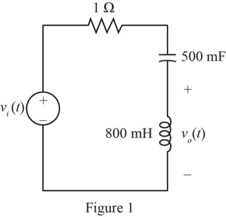
The input voltage is,
The given diagram is shown in Figure 1.
Calculation:
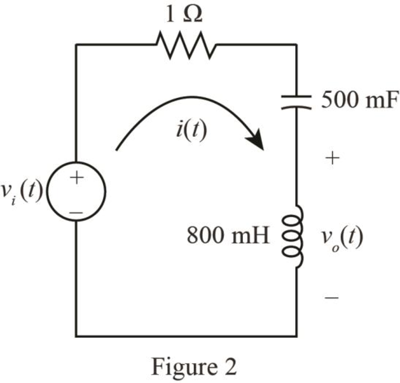
Mark the loop current
The required diagram is shown in Figure 2.
The conversion of
The conversion of
Hence, the value of the inductor,
The conversion of
The conversion of
Hence, the value of the capacitor,
The expression for output voltage using KVL is given by,
Substitute
Apply Fourier transform to the above expression.
The Fourier transform of
Substitute
Further solve as,
Apply shifting property for
Further solve as,
The inverse Fourier transform for the
The inverse Fourier transform for the
The inverse Fourier transform for the
Substitute
The expression for the output voltage from the figure is given by,
Substitute
Further solve as,
Conclusion:
Therefore, the value of output voltage,
(b)
The value of output voltage,
(b)
Answer to Problem 61E
The value of output voltage,
Explanation of Solution
Given data:
The input voltage is,
Calculation:
The expression for output voltage using KVL is given by,
Substitute
Apply Fourier transform to the above expression.
The Fourier transform of
Substitute
Further solve as,
The inverse Fourier transform for the
The inverse Fourier transform for the
Substitute
The expression for the output voltage from the figure is given by,
Substitute
Further solve as,
Conclusion:
Therefore, the value of output voltage,
Want to see more full solutions like this?
Chapter 17 Solutions
Loose Leaf for Engineering Circuit Analysis Format: Loose-leaf


- Evaluate the Fourier transform, X(jω), of the following signal,x(t):arrow_forwardLet a > 0, show that the Fourier transform of f (ax) is F (μ/a)/aarrow_forwardRegarding Signals and Systems, given a signal x(t) = |cos(ωt)| for ω>0. Find the Fourier transform of x(t). Please do not ignore the absolute value operator (that is what I am struggling with.arrow_forward
- Fast Fourier transform technique is used in the spectrum analyzers to determine/measure the lower order harmonics. True Falsearrow_forwardGiven the finite-duration sequence below, x[n]={-4,1,2,0,3} where -4 is when n=0, if it has a fourier transform of X(w) , what is the value of X(0)?arrow_forwardBe able to calculate the Fourier transform of a function Find the Fourier transform of each function. In each case, a is a positive real constant.f(t)=0,t<0,f(t)=e−atsin ω0t,t≥0.arrow_forward
- x [n] = [1,5,2,3,3,1,2,3]Find the Fourier coefficients for the discrete time signal given by the fast Fourier transform.arrow_forwardFor the system given in Fig. 2, determine the Fourier Transform of the system, i.e., system transfer function.arrow_forwardFind the Fourier transform of the signal below. Show the details of your work. Write your answer on a white typewriting paper, scan it in JPEG format, and paste it into the space provided below. f(t) = 10rect(t – 8)arrow_forward
- Obtain the inverse Fourier transform ofarrow_forward1. Obtain the inverse Fourier transform of the given function.arrow_forwarddear expert, at first you can use any "suitable application" like nodal analysis, mesh analysis, KCL , KVL etc. then, proceed it to "fourier series analysis' that's it. thanksarrow_forward
 Introductory Circuit Analysis (13th Edition)Electrical EngineeringISBN:9780133923605Author:Robert L. BoylestadPublisher:PEARSON
 Delmar's Standard Textbook Of ElectricityElectrical EngineeringISBN:9781337900348Author:Stephen L. HermanPublisher:Cengage Learning
 Programmable Logic ControllersElectrical EngineeringISBN:9780073373843Author:Frank D. PetruzellaPublisher:McGraw-Hill Education
 Fundamentals of Electric CircuitsElectrical EngineeringISBN:9780078028229Author:Charles K Alexander, Matthew SadikuPublisher:McGraw-Hill Education
 Electric Circuits. (11th Edition)Electrical EngineeringISBN:9780134746968Author:James W. Nilsson, Susan RiedelPublisher:PEARSON
 Engineering ElectromagneticsElectrical EngineeringISBN:9780078028151Author:Hayt, William H. (william Hart), Jr, BUCK, John A.Publisher:Mcgraw-hill Education,