
Concept explainers
Videos
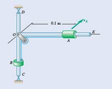
Calculate the angular velocity of frame and moment of inertia of pulley and frame about rod CD.Coller A and B slide on frame collars are attached by a cord to slide over a frame.
Answer to Problem 17.89P
Angular velocity of the frame is
Explanation of Solution
Given information:
Mass of coller A =
Mass of coller B =
The velocity of coller A at position
Concept used:
Conservation of angular momentum.
Conservation of energy.
calculation:
component of velocity for coller A,
For position 1,
From equation (1),
Potential energy,
Kinetic energy,
Angular momentum,
For position 2,
Potential energy,
Kinetic energy,
Angular momentum,
By conservation of angular momentum,
By conservation of energy,
Further solving we get
Considering only the positive value.
Hence,
Moment of inertia of pulley and frame is 0.0507 kg.m2
To find the angular velocity of the frame, we have
Conclusion:
By applying conservation of angular momentum and conservation of energy for initial and find the position of coller relative to the frame we get,
Angular velocity of the frame is
Want to see more full solutions like this?
Chapter 17 Solutions
Vector Mechanics For Engineers


- Two identical giant flywheels are on 2 identical slopes at an angle alpha = 20 deg. One flywheel is rolling on its inside shaft of diameter d1 = 3 ft, and the second flywheel is rolling without slipping on its outside diameter d2 = 5 ft. They are both released from rest. The weight of the flywheel is W = 8 lbs 1. Knowing that flywheel 1 attains a speed of v = 7.0 ft/s in t = [t] s, (if t doesn't show take any t between 5 and 10 sec) find the radius of gyration of the flywheels, following those steps: 3. What will be the distance between the 2 flywheels? Which one is in front? a. Explain your strategy to find the distance made by each wheel. b. Find the 3 distances made by each wheel. c. Find the distance between the 2 flywheels. d. Why one is in front? 4. Using flywheel 2, what is the coefficient of static friction between the outside diameter and the ground required to prevent slipping? a. Using the 3 previous diagrams, which impulse will you consider finding the force of…arrow_forwardThe 10-Ib sphere and 7-ib block (shown in section) are secured to the arm of negligible mass which rotates in the vertical plane about a horizontal axis at O. The 5-Ib plug is released from rest at A and falls into the recess in the block when the arm has reached thehorizontal position. An instant before engagement, the arm has an angular velocity wo = 1.2 rad/s. Determine the angular velocity w(positive if counterclockwise, negative if clockwise) of the arm immediately after the plug has wedged itself in the block.arrow_forwardThe 2.00-kg slender rod shown is hanging in a vertical position and is pin-supported at point A. The slender rod is initially at rest until a 1.000-kg block C, strikes it at its end at point B.The block slides on a frictionless surface with a velocity of 3.50 m/s to the right. After the impact, it slides with a velocity of 1.250 m/s to the right, and the bar rotates with an angular velocity, ω'. 1. What gives the correct kinematic relationship relating the final velocity of the center of the rod, v' , and its angular velocity, ω'? 2. What is the coefficient of restitution, e, between the block and the slender rod? 3. What is the magnitude of the horizontal impulse at the support at point A?arrow_forward
- A small sphere of mass ma and radius r is released from rest at A and rolls without sliding on the curved surface to point B where it leaves the surface with a horizontal velocity. Knowing that b = 1.2 m, determine (a ) the speed of the sphere as it strikes the ground at C (b) the corresponding distance c.arrow_forwardThe motion of the uniform rod AB is guided by small wheels of negligible mass that roll on the surface shown. If the rod is released from rest when 0 = 0, determine the velocities of A and B when 0= 30°.arrow_forwardA particle M1, weighing 2.4 Ibs, is tied to a thread and describes a circular path in a horizontal plane. The thread, of negligible mass, passes through a hole in the center of the circle and descends vertically. Another particle M2 is attached, weighing 5.0 Ibs, as shown in the figure. If M1 describes a uniform circular motion, with angular velocity w 3.1 rad/s, determine the radius R of the circumference in inches.arrow_forward
- A 5-m-long ladder has a mass of 15 kg and is placed against a house at an angle 0 = 20°. Knowing that the ladder is released from rest, determine the angular velocity of the ladder and the velocity of end A when 0 = 45°. Assume the ladder can slide freely on the horizontal ground and on the vertical wall.arrow_forwardDynamic Problem, reply as soon as posible. The double pulley system weighs 30 lbs. and has a 6.5-inch center radius of gyration. Cylinders A and B areconnected to the double pulley by cords that wrap around the circles whose radii are shown. Thecoefficient of kinetic friction between block B and the surface is 0.25. If the system is released from rest atposition shown, determine:A) The velocity of cylinder A just before hitting the ground.B) The total distance cylinder B travels before coming to rest.arrow_forwardA ball of mass (m) is connected by a light string of length (L) to a frictionless pivot point P and swings as a pendulum as shown in Fig. (1). The ball is released from rest at point A when the string makes an angle of e with vertical. Determine; 1) The velocity of the ball as it passes through point B. 2) The tension TA in the string at A. 3) The tension Te in the string at B.arrow_forward
- Disk A rotates in a horizontal plane about a vertical axis at the constant rate 00. Slider B has a mass m and moves in a frictionless slot cut in the disk. The slider is attached to a spring of constant k , which is undeformed when r= 0. Knowing that the slider is released with no radial velocity in the position r=r0,, draw a FBD and KD at an arbitrary distance r from 0.arrow_forwardIn the engine system shown l = 250 mm and b = 100 mm. The connecting rod BD is assumed to be a 1.2-kg uniform slender rod and is attached to the 1.8-kg piston P. During a test of the system, crank AB is made to rotate with a constant angular velocity of (400) rpm CW with no force applied to the face of the piston. Determine the velocity and acceleration of the piston P when θ = 90°. (Neglect the effect of the weight of the rod.)arrow_forward
 Elements Of ElectromagneticsMechanical EngineeringISBN:9780190698614Author:Sadiku, Matthew N. O.Publisher:Oxford University Press
 Mechanics of Materials (10th Edition)Mechanical EngineeringISBN:9780134319650Author:Russell C. HibbelerPublisher:PEARSON
 Thermodynamics: An Engineering ApproachMechanical EngineeringISBN:9781259822674Author:Yunus A. Cengel Dr., Michael A. BolesPublisher:McGraw-Hill Education
 Control Systems EngineeringMechanical EngineeringISBN:9781118170519Author:Norman S. NisePublisher:WILEY
 Mechanics of Materials (MindTap Course List)Mechanical EngineeringISBN:9781337093347Author:Barry J. Goodno, James M. GerePublisher:Cengage Learning
 Engineering Mechanics: StaticsMechanical EngineeringISBN:9781118807330Author:James L. Meriam, L. G. Kraige, J. N. BoltonPublisher:WILEY