
Concept explainers
Videos
In a game of pool, ball A is rolling without slipping with a velocity
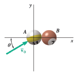
Fig. P17.133
a)
The linear and angular velocity of each ball immediately after the impact.
Answer to Problem 17.133P
The linear velocity of ball A immediately after the impact is
The angular velocity of ball A immediately after the impact is
The linear velocity of ball B immediately after the impact is
The angular velocity of ball B immediately after the impact is
Explanation of Solution
Given information:
The mass of the each ball is m.
The radius of the each ball is r.
The velocity of the ball A before the impact is
The coefficient of kinetic friction between a ball and the table
Calculation:
Write the equation of moment of inertia
Analyze the impact of ball A.
Here, G is the mass center of ball A.
Consider the conservation of momentum principle.
Sketch the impulse and momentum diagram of the ball A as shown in Figure 1.
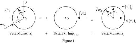
Here,
Refer Figure (1).
Consider the kinematics in position 1.
Write the equation of angular velocity
Consider the horizontal components of forces.
Consider the vertical components of forces.
Take moments about y axis.
Take moments about x axis.
Analyze the impact of ball B.
Here, G is the mass center of ball B.
Consider the conservation of momentum principle.
Sketch the impulse and momentum diagram of the ball B as shown in Figure (2).
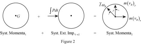
Here,
Refer Figure (2),
Consider the horizontal components of forces.
Consider the vertical components of forces.
Take moments about y axis.
Take moments about x axis.
Add Equations (1) and (5).
The impact is perfectly plastic. Therefore ,the coefficient of restitution (e) is 1.
Consider the condition of impact equation.
Substitute 1 for e.
Find the horizontal components of linear velocity
Solve Equations (9) and (10) simultaneously.
Add Equations (9) and (10).
Find the horizontal components linear velocity
Substitute
Find the vertical components of linear velocity
Find the vertical components of linear velocity
Find the linear velocity
Substitute 0 for
Thus, the linear velocity of ball A immediately after the impact is
Find the linear velocity
Substitute
Thus, the linear velocity of ball B immediately after the impact is
Find the initial angular velocity of ball A using kinematics.
Find the angular velocity
Solve Equations (3) and (4) simultaneously.
Add Equations (3) and (4).
Substitute
Thus, the angular velocity of ball A immediately after the impact is
Find the angular velocity
From Equations (7) and (8).
Thus, the angular velocity of ball B immediately after the impact is
b)
Find the velocity of ball B after it has started rolling uniformly.
Answer to Problem 17.133P
The velocity of ball B after it has started rolling uniformly is
Explanation of Solution
Calculation:
Consider the motion after impact of ball B.
Consider C is the mass center of ball A.
Consider the conservation of momentum principle.
Sketch the motion of impulse and momentum diagram of the ball A after the impact as shown in Figure (3).
Here,
Consider the condition of rolling without slipping in kinematics.
Refer Figure (3).
Take moments about C:
Substitute
Find the velocity of sphere A after it has started rolling uniformly using the equation:
Substitute
Thus, the velocity of ball A after it has started rolling uniformly is
Consider the motion after impact of ball A.
Consider C is the mass center of ball A.
Consider the conservation of momentum principle.
Sketch the motion of impulse and momentum diagram of the ball B after the impact as shown in Figure (3).

Here, N is the normal force on ball A, F is the friction force between ball and floor, t is the rolling time,
Consider the condition of rolling without slipping in kinematics.
Refer Figure (3),
Take moments about C:
Substitute
Find the velocity of sphere B after it has started rolling uniformly using the equation:
Substitute
Thus, the velocity of sphere B after it has started rolling uniformly is
Want to see more full solutions like this?
Chapter 17 Solutions
Vector Mechanics for Engineers: Statics and Dynamics
Additional Engineering Textbook Solutions
DeGarmo's Materials and Processes in Manufacturing
Engineering Mechanics: Statics
Fundamentals Of Thermodynamics
Thermodynamics: An Engineering Approach
Automotive Technology: Principles, Diagnosis, And Service (6th Edition) (halderman Automotive Series)
Introduction To Finite Element Analysis And Design


- A 5-m-long ladder has a mass of 15 kg and is placed against a house at an angle 0 = 20°. Knowing that the ladder is released from rest, determine the angular velocity of the ladder and the velocity of end A when 0 = 45°. Assume the ladder can slide freely on the horizontal ground and on the vertical wall.arrow_forwardDisk A, of weight 5 lb and radius r = 3 in., is at rest when it is placed in contact with a belt that moves at a constant speed v = 50 ft/s. Knowing that μk = 0.20 between the disk and the belt, determine the time required for the disk to reach a constant angular velocity.arrow_forwardA disk of radius r rolls to the right with a constant velocity v. Denoting by P the point of the rim in contact with the ground at t = 0, derive expressions for the horizontal and vertical components of the velocity of P at any time t.arrow_forward
- At the instant shown in Fig. TT1.3, during deceleration, the velocity of an automobile is 13.3 m/s to the right. Knowing that the velocity of the contact point A of the wheel with the ground is 2.2 m/s to the right, determine the location of the instantaneous center of rotation of the wheel below point O in mm. Fig. TT1.3: A wheel in contact with the ground.arrow_forwardA helicopter moves horizontally in the x direction at a speed of 120 mi/h. Knowing that the main blades rotate clockwise when viewed from above with an angular velocity of 180 rpm, determine the instantaneous axis of rotation of the main blades.arrow_forwardA painter is half way up a 10-m ladder when the bottom starts sliding out from under him. Knowing that point A has a velocity vA = 2 m/s directed to the left when 0= 60°, determine (a) the angular velocity of the ladder, (b) the velocity of the painter.arrow_forward
- A long-range ballistic trajectory between points A and B on the earth’s surface consists of a portion of an ellipse with the apogee at point C. Knowing that point C is 1500 km above the surface of the earth and the range Rφ of the trajectory is 6000 km, determine (a) the velocity of the projectile at C, (b) the eccentricity ε of the trajectory.arrow_forwardPlease answer this NEATLY, COMPLETELY, and CORRECTLY for an UPVOTE. Two spheres A and B (of mass m each) were fired vertically from the ground with different initial velocities at different times. When sphere A reached its summit, sphere B, with an upward velocity of 10.76 m/s, created a head-on collision with A. The impact caused sphere A to break into two pieces, each of mass m/2. Knowing one-piece reached Point C and the other piece reached point D after the collision, determine: (a) the velocity of sphere B after the collision; (b) the angle θ and the speeds of the two pieces after the collision; and (c) the force exerted by sphere A on B if the collision occurred in 0.001s.arrow_forwardSphere A, which has an angular and linear velocity of 57.1 rad/s and 2.85 m/s, respectively, rolls without sliding and hits a slender Bar B of mass m_B = 1.00 kg and length L = 0.12 m, which is initially at rest as shown in the following figure. Neglecting the friction between the sphere and the bar, and knowing the coefficient of restitution between the sphere and the bar is 0.2, determine (1) the angular velocity of Bar B immediately after impact, and (2) the linear velocities of sphere A and bar B immediately after impact (and at their centroids).arrow_forward
- A helicopter moves vertically in the y direction at a speed of 10 km/h. Knowing that the main blades rotate clockwise with an angular velocity of 180 rpm, and the assistive blades rotate counterclockwise with an angular velocity of 200 rpm, determine; a) the instantaneous axis of rotation of the main blades, b) the instantaneous axis of rotation of the assistive blades.arrow_forwardA spring AB of constant k=200kn/m is attached to a support at A and to a collar of mass m=200 gm. The unstretched length of the spring is I=0.6m. Knowing that the collar is released from rest at x0 = 80 cm and neglecting friction between the collar and the horizontal rod, determine :the magnitude of the velocity of the collar as it passes through point C.arrow_forwardIn order to uncoil electrical wire from a 0.6-m-radius spool fixed to a truck, a worker drives to the left with a speed of vA = 5 m/s. At the same time, a second worker holds the cable as he walks to the right with a speed of vB = 3 m/s. Knowing that at the instant shown the thickness of wire on the spool is 40 mm, determine (a) the instantaneous center of rotation of the spool, (b) the velocity of point D on the inside of the spool.arrow_forward
 Elements Of ElectromagneticsMechanical EngineeringISBN:9780190698614Author:Sadiku, Matthew N. O.Publisher:Oxford University Press
 Mechanics of Materials (10th Edition)Mechanical EngineeringISBN:9780134319650Author:Russell C. HibbelerPublisher:PEARSON
 Thermodynamics: An Engineering ApproachMechanical EngineeringISBN:9781259822674Author:Yunus A. Cengel Dr., Michael A. BolesPublisher:McGraw-Hill Education
 Control Systems EngineeringMechanical EngineeringISBN:9781118170519Author:Norman S. NisePublisher:WILEY
 Mechanics of Materials (MindTap Course List)Mechanical EngineeringISBN:9781337093347Author:Barry J. Goodno, James M. GerePublisher:Cengage Learning
 Engineering Mechanics: StaticsMechanical EngineeringISBN:9781118807330Author:James L. Meriam, L. G. Kraige, J. N. BoltonPublisher:WILEY