
Concept explainers
Videos
The dynamic reaction at D (D) and E (E).
Answer to Problem 18.153RP
The dynamic reaction at D (D) and E (E) are
Explanation of Solution
Given Information:
The weight of the disk (W) is 6 lb.
The constant angular velocity
The constant angular velocity
The radius (r) of the disk is
The length (l) of the rod is
The length of the rod from disk to point B (b) and B to C (c) is
Assume the acceleration due to gravity (g) as
Calculation:
Write the expression for the angular velocity
Write the expression for the angular velocity
Write the expression the centroidal moment of inertia
Write the expression the centroidal moment of inertia
Write the express the angular moment
Substitute
Let the reference frame Oxyz be rotating with angular velocity
Write the express the angular momentum
Substitute
Write the express the rate of change of angular
Substitute
Write the expression for the position vector
Write the expression for the velocity
Substitute
Write the expression for the acceleration
Substitute
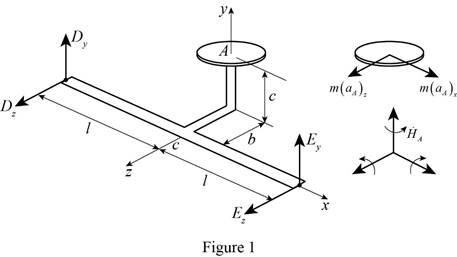
Show the impulse momentum diagram as in Figure (1).
Write the expression for the sum of the forces:
Substitute
Resolve the i and k component,
Express the moment about the point D.
Write the expression for the position vector
Write the expression for the sum of the moment about D:
Substitute
Resolve the component i, j and k component.
For i component,
For j component,
For k component,
Calculate the mass of the disk (m) using the relation:
Substitute 6lb for W and
Differentiate the angular velocity of
Differentiate the angular velocity of
Calculate the z component dynamic reaction
Substitute  ,
,
Calculate the y component dynamic reaction
Substitute
Calculate the y component dynamic reaction
Substitute
Calculate the z component dynamic reaction
Substitute
Calculate the dynamic reaction (D) at D:
Substitute
Calculate the dynamic reaction (E) at E:
Substitute
Thus, the dynamic reaction at D (D) and E (E) are
Want to see more full solutions like this?
Chapter 18 Solutions
VECTOR MECH...,STAT.+DYNA.(LL)-W/ACCESS


- An automobile wheel test rig consists of a uniform disk A, of mass mà = 5000 kg and radius rà = 1.5 m, that can rotate freely about its fixed center C and over which the wheel of an automobile is made to roll. A wheel B, whose center and center of mass coincide at D, is mounted on a shaft (not shown) that holds D fixed while it allows the wheel to rotate about D. The wheel has diameter d = 0.62 m, mass mß = 21.5 kg, and mass moment of inertia about its mass center /D = 44 kg-m². Both A and B are initially at rest when B is subject to a constant torque M that causes B to roll without slip on A. M B d A If M = 1200 N·m, use the angular impulse-momentum principle to determine how long it takes to reach conditions simulating a car speed of 100 km/h. The automobile wheel test rig takes s to reach conditions simulating a car speed of 100 km/h.arrow_forwardAn automobile wheel test rig consists of a uniform disk A, of mass mд = 5000 kg and radius rà = 1.5 m, that can rotate freely about its fixed center C and over which the wheel of an automobile is made to roll. A wheel B, whose center and center of mass coincide at D, is mounted on a shaft (not shown) that holds D fixed while it allows the wheel to rotate about D. The wheel has diameter d = 0.62 m, mass mß = 21.5 kg, and mass moment of inertia about its mass center /D = 44 kg.m². Both A and B are initially at rest when B is subject to a constant torque M that causes B to roll without slip on A. M BC B TA If M = 1200 N.m, use the angular impulse-momentum principle to determine how long it takes to reach conditions simulating a car speed of 100 km/h. The automobile wheel test rig takes 17.95 s to reach conditions simulating a car speed of 100 km/h.arrow_forwardA homogeneous disk of weight W = 6 lb rotates at the constant rate w1 = 16 rad/s with respect to arm ABC, which is welded to a shaft DCE rotating at the constant rate w2 = 8 rad/s. Determine the dynamic reactions at D and E.arrow_forward
- A shaft turning at a uniform speed carries two uniform discs A and B of masses 10kg and 8kg respectively. The centres of the mass of the discs are each 2.5mm from the axis of rotation. The radii to the centres of mass are at right angles. The shaft is carried in bearings C and D between A and B such that AC = 0.3m, AD = 0.9m and AB = 1.2m. It is required to make dynamic loading on the bearings equal and a minimum for any given shaft speed by adding a mass at a radius 25mm in a plane E. Determine: The dynamic loading on each bearing when the mass in plane E has been attached and the shaft rotates at 200 rev/min. For the bearing loads in the opposite direction determine all the unknown values. For the bearing loads in the same direction, show the diagrams and equations only to use for a possible solution. PS – Use graphical methods to solve the balancing problemarrow_forwardA shaft turning at a uniform speed carries two uniform discs A and B of masses 10kg and 8kg respectively. The centres of the mass of the discs are each 2.5mm from the axis of rotation. The radii to the centres of mass are at right angles. The shaft is carried in bearings C and D between A and B such that AC = 0.3m, AD = 0.9m and AB = 1.2m. It is required to make dynamic loading on the bearings equal and a minimum for any given shaft speed by adding a mass at a radius 25mm in a plane E. Determine: The magnitude of the mass in plane E and its angular position relative to the mass in plane A The distance of the plane E from plane A PS – Use graphical methods to solve the balancing problemarrow_forwardA shaft turning at a uniform speed carries two uniform discs A and B of masses 10kg and 8kg respectively. The centres of the mass of the discs are each 2.5mm from the axis of rotation. The radii to the centres of mass are at right angles. The shaft is carried in bearings C and D between A and B such that AC = 0.3m, AD = 0.9m and AB = 1.2m. It is required to make dynamic loading on the bearings equal and a minimum for any given shaft speed by adding a mass at a radius 25mm in a plane E. Determine: (a) The magnitude of the mass in plane E and its angular position relative to the mass in plane (b) The distance of the plane E from plane A (c) The dynamic loading on each bearing when the mass in plane E has been attached and the shaft rotates at 200 rev/min. For the bearing loads in the opposite direction determine all the unknown values. For the bearing loads in the same direction, show the diagrams and equations only to use for a possible solution. PS - Use graphical methods to solve the…arrow_forward
- A shaft turning at a uniform speed carries two uniform discs A and B of masses 10kg and 8kg respectively. The centres of the mass of the discs are each 2.5mm from the axis of rotation. The radii to the centres of mass are at right angles. The shaft is carried in bearings C and D between A and B such that AC = 0.3m, AD = 0.9m and AB = 1.2m. It is required to make dynamic loading on the bearings equal and a minimum for any given shaft speed by adding a mass at a radius 25mm in a plane E. Determine: (a) The magnitude of the mass in plane E and its angular position relative to the mass in plane A (b) The distance of the plane E from plane A (c) The dynamic loading on each bearing when the mass in plane E has been attached and the shaft rotates at 200 rev/min. For the bearing loads in the opposite direction determine all the unknown values. For the bearing loads in the same direction, show the diagrams and equations only to use for a possible solution.arrow_forwardA shaft turning at a uniform speed carries two uniform discs A and B of masses 10kg and 8kg respectively. The centres of the mass of the discs are each 2.5mm from the axis of rotation. The radii to the centres of mass are at right angles. The shaft is carried in bearings C and D between A and B such that AC = 0.3m, AD = 0.9m and AB = 1.2m. It is required to make dynamic loading on the bearings equal and a minimum for any given shaft speed by adding a mass at a radius 25mm in a plane E. Determine: The magnitude of the mass in plane E and its angular position relative to the mass in plane A The distance of the plane E from plane A The dynamic loading on each bearing when the mass in plane E has been attached and the shaft rotates at 200 rev/min. For the bearing loads in the opposite direction determine all the unknown values. For the bearing loads in the same direction, show the diagrams and equations only to use for a possible solution. PS – Use graphical methods to solve the…arrow_forwardA shaft turning at a uniform speed carries two uniform discs A and B of masses 10kg and 8kg respectively. The centres of the mass of the discs are each 2.5mm from the axis of rotation. The radii to the centres of mass are at right angles. The shaft is carried in bearings C and D between A and B such that AC = 0.3m, AD = 0.9m and AB = 1.2m. It is required to make dynamic loading on the bearings equal and a minimum for any given shaft speed by adding a mass at a radius 25mm in a plane E. USING THE METHOD OF DRAWING m*r and m*r*l diagram Determine: The magnitude of the mass in plane E and its angular position relative to the mass in plane A The distance of the plane E from plane A The dynamic loading on each bearing when the mass in plane E has been attached and the shaft rotates at 200 rev/min. For the bearing loads in the opposite direction determine all the unknown values. For the bearing loads in the same direction, show the diagrams and equations only to use for a possible…arrow_forward
- A uniform square plate with side a= 300 mm is hinged at points A and B to a clevis that rotates with a constant angular velocity w about a vertical axis. Determine (a) the value of w for which the plate forms a constant angle β= 60° with the horizontal x axis, (b) the largest value of w for which the plate remains vertical (β= 90°).arrow_forward4. The link EF of mass 2 kg is welded at point A to a link ABC of mass 2 kg, which rotates about a pivot B. A spring of constant k =300 N/m and of un-stretched length 150 mm is attached to the link ABC as shown. Knowing that in the position shown the assembly has an angular velocity of 10 rad/s clockwise, (a) Determine the angular velocity when the assembly has rotated 90° clockwise, (b) Find the corresponding angular acceleration of part (a), and (c) Find the corresponding reaction force at point B. (For (b) and (c), set up all the required equations with a Free-Body-Diagram 150 mm and a Kinetic Diagram) 150 mm, 150 mm, E 150 mm 360 mmarrow_forwardA stationary horizontal plate is attached to the ceiling by means ofa fixed vertical tube. A wheel of radius aa and mass mm is mounted on a light axle ACAC that is attached by means of a clevis at AA to a rod ABAB fitted inside the vertical tube. The rod ABAB is made to rotate with a constant angular velocity ΩΩ causing the wheel to roll on the lower face of the stationary plate. Determine the minimum angular velocity ΩΩ for which contact is maintained between the wheel and the plate. Consider the particular cases ( aa ) when the mass of the wheel is concentrated in the rim, (b) when the wheel is equivalent to a thin disk of radius aa also extend the problem using Kinematic and Kinetic analysisarrow_forward
 Elements Of ElectromagneticsMechanical EngineeringISBN:9780190698614Author:Sadiku, Matthew N. O.Publisher:Oxford University Press
 Mechanics of Materials (10th Edition)Mechanical EngineeringISBN:9780134319650Author:Russell C. HibbelerPublisher:PEARSON
 Thermodynamics: An Engineering ApproachMechanical EngineeringISBN:9781259822674Author:Yunus A. Cengel Dr., Michael A. BolesPublisher:McGraw-Hill Education
 Control Systems EngineeringMechanical EngineeringISBN:9781118170519Author:Norman S. NisePublisher:WILEY
 Mechanics of Materials (MindTap Course List)Mechanical EngineeringISBN:9781337093347Author:Barry J. Goodno, James M. GerePublisher:Cengage Learning
 Engineering Mechanics: StaticsMechanical EngineeringISBN:9781118807330Author:James L. Meriam, L. G. Kraige, J. N. BoltonPublisher:WILEY