
Concept explainers
Find the consolidation settlement of the group.
Answer to Problem 18.25P
The consolidation settlement of the group is
Explanation of Solution
Given information:
The total load
The length
The length
The length
The unit weight
The saturated unit weight
The initial void ratio
The coefficient of consolidation
The saturated unit weight
The initial void ratio
The coefficient of consolidation
The saturated unit weight
The initial void ratio
The coefficient of consolidation
The saturated unit weight
The initial void ratio
The coefficient of consolidation
Calculation:
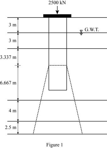
Show the pressure diagram as in Figure 1.
Determine the total length L of pile using the formula.
Substitute 3 m for
The load starts transmitting to the soil at the pile depth of
Determine the depth at which the load on the group pile
Here, L is the depth of normally consolidated clay layer 1.
Substitute 10 m for L.
Thus, the settlement starts in NCC layer 1.
Determine the stress
Here,
Take the unit weight of water as
Substitute
Determine the stress
Here,
Substitute
Determine the stress
Here,
Substitute
Calculate the stress
Here,
Substitute 2,500 kN for
Calculate the stress
Substitute 2,500 kN for
Calculate the stress
Substitute 2,500 kN for
Determine the value of
Substitute
Determine the value of
Substitute
Determine the value of
Substitute
Determine the consolidated settlement
Here,
Substitute 0.30 for
Determine the consolidated settlement
Here,
Substitute 0.35 for
Determine the consolidated settlement
Here,
Substitute 0.26 for
Determine the total
Substitute 0.186 m for
Therefore, the consolidated settlement of the group pile is
Want to see more full solutions like this?
Chapter 18 Solutions
Fundamentals of Geotechnical Engineering (MindTap Course List)


- Refer to Figure 18.26b. Let L = 15.24 m, fill = 17.29 kN/m3, sat(clay) = 19.49 kN/m3, clay = 20, Hf = 3.05 m, and D = 0.406 m. The water table coincides with the top of the clay layer. Determine the total downward drag on the pile. Assume that = 0.6 clay. FIG. 18.26 Negative skin frictionarrow_forwardFigure P12.36 shows a 3 5 pile group consisting of 15 concrete piles of 400 mm diameter and 12 m in length. What would be the maximum load that can be allowed on the mat with a factor of safety of 3? The piles have a center-to-center spacing of 1200 mm.arrow_forwardRefer to Figure 18.13. Given L1 = 1.5 m, L2 = 3 m; for the sand, =33, =16.5kN/m3, sat=19.0kN/m3; and, for the clay, c=50kN/m2, =0, sat=20kN/m3. Determine the depth of sheet pile required, allowing for a 50% increase from the theoretical estimate.arrow_forward
- Figure 18.26a shows a pile. Let L = 20 m, D = 450 mm. Hf = 4m, f = 17.5 kN/m3, fill = 25. Determine the total downward drag force on the pile. Assume that the fill is located above the water table and that = 0.5 fill. FIG. 18.26 Negative skin frictionarrow_forwardFigure 18.39 shows a 3 5 pile group consisting of 16 concrete piles of 400 mm diameter and 12 m in length. What would be the maximum load that can be allowed on the mat with a factor of safety of 3? The piles have center-to-center spacing of 1200 mm. FIG. 18.39arrow_forwardA 600 mm diameter and 25 m long driven concrete pile carries a column load of 1200 kN. It is estimated that the shaft carries 900 kN and the point carries 300 kN. Determine the settlement of the pile head using the Poulos and Davis method with the following data: Es = 25 MN/m2, Ep = 30,000 MN/m2, and s = 0.2arrow_forward
- Determine the maximum load that can be allowed on the 450 mm diameter pile shown in Figure 18.36, with a safety factor of 3. Use the a method for computing the shaft friction. FIG. 18.36arrow_forwardRefer to Figure 9.42b. Let L = 18 m, γfill = 17 kN/m3, γsat(clay) = 19.8 kN/m3, Φ'clay = 20°, Hf = 3.5 m, and D (pile diameter) = 406 mm. The water table coincides with the top of the clay layer. Determine the total downward drag force on the pile. Assume ẟ' = 0.6 Φ'clay.arrow_forwardIn Hiley’s formula for driven piles i.e. R=E/(s+0.5c), why is a coefficient of 0.5 applied for the term elastic deformation of piles and soil?arrow_forward
- The Figure below shows a long pile wall driven in sand with Coefficient of permeability K= 0.05cm/sec.it is required to: 1.Estimate the max. possible value of dimension h, where Ah=1.2. 2.Calculate the seepage loss (m /day) per meter of wallarrow_forwardPlease help me solve3.8 The soil profi le at a site for an offshore structure is shown in Figure P13.8. The height of the pile above the sand surface is 15 m. Determine the allowable load for a driven closed-ended pipe pile with diameter 1.25 m and embedded 10 m into the stiff clay. A factor of safety of 2 is requiredarrow_forwarda group of 9 piles of 29 cm diameter is arranged in a square configuration with a center-to-center spacing of 1.86 m. The length of the piles is 11 m. Unit cohesion of the clay is 86 kPa. Determine the ultimate group capacity of the pile group based on block failure. Assume adhesion factor of 0.7.arrow_forward
 Fundamentals of Geotechnical Engineering (MindTap...Civil EngineeringISBN:9781305635180Author:Braja M. Das, Nagaratnam SivakuganPublisher:Cengage Learning
 Principles of Foundation Engineering (MindTap Cou...Civil EngineeringISBN:9781337705028Author:Braja M. Das, Nagaratnam SivakuganPublisher:Cengage Learning
 Principles of Foundation Engineering (MindTap Cou...Civil EngineeringISBN:9781305081550Author:Braja M. DasPublisher:Cengage Learning
 Principles of Geotechnical Engineering (MindTap C...Civil EngineeringISBN:9781305970939Author:Braja M. Das, Khaled SobhanPublisher:Cengage Learning