Videos
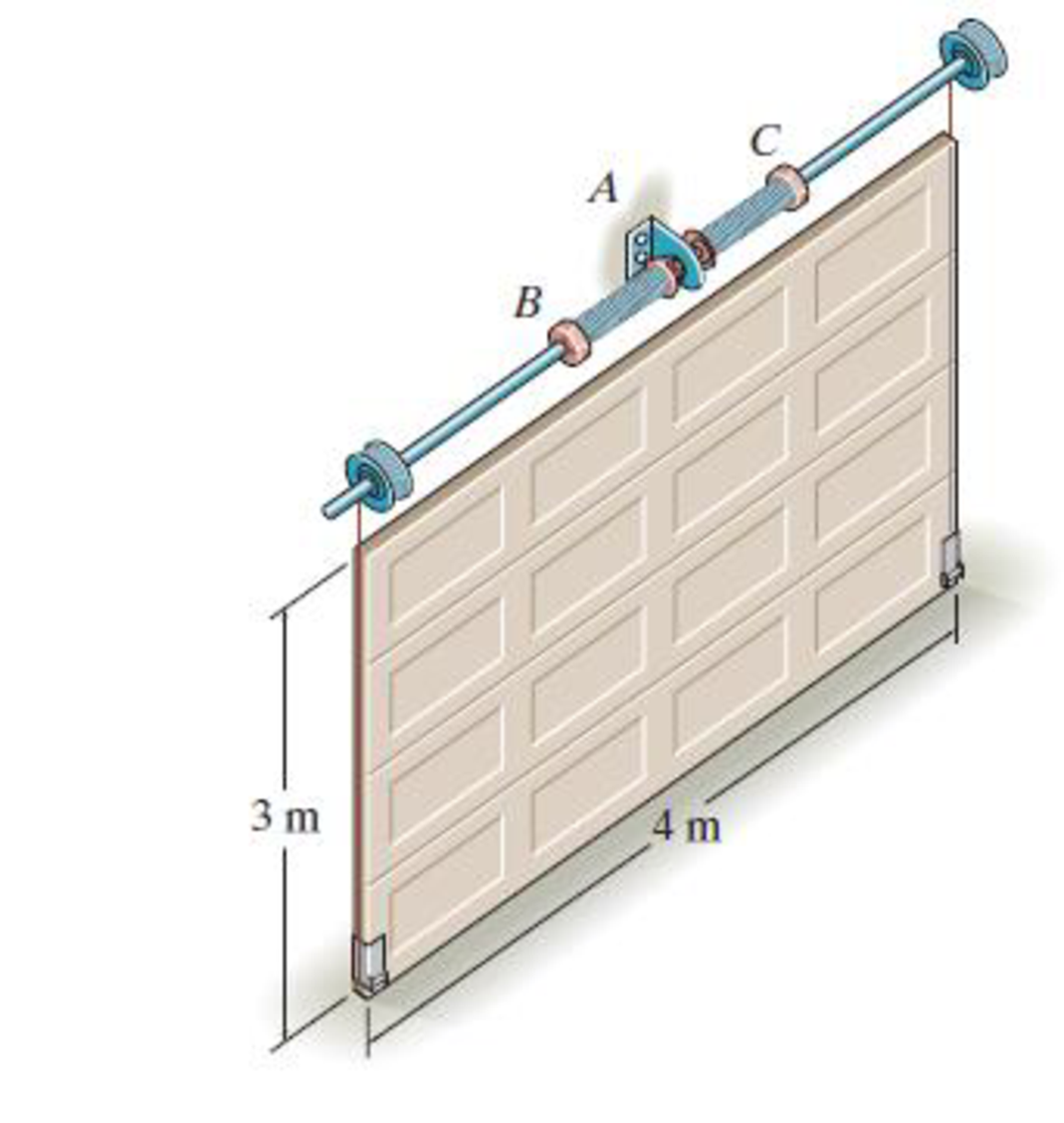
Lifting is done using the two springs, each of which is attached to the anchor bracket at A and to the counterbalance shaft at B and C. As the door is raised, the springs begin to unwind from the shaft, thereby assisting the lift. If each spring provides a torsional moment of M = (0.7θ) N·m, where θ is in radians, determine the angle θ0 at which both the left-wound and right-wound spring should be attached so that the door is completely balanced by the springs, i.e , when the door is in the vertical position and is given a slight force upward, the springs will lift the door along the side tracks to the horizontal plane with no final angular velocity. Note: The elastic potential energy of a torsional spring is
Want to see the full answer?
Check out a sample textbook solution
Chapter 18 Solutions
Engineering Mechanics: Dynamics; Modified Mastering Engineering with Pearson eText -- Standalone Access Card -- for Engineering Mechanics: Dynamics (14th Edition)


- The left and right strings have a mass of 0.01 kg, the middle string has a mass of 0.02 kg. Both theta and beta angles are 40 degrees. Show the calculations used to determine the horizontal and vertical components of the tension forces connected to the center string.arrow_forwardThe ideal spring of constant k=2.6kN/m is attached to the fitted at point A and the end fitted at point B, as shown. The spring is unstretched when theta(A) and theta(B) are both zero. If the fitted is rotated 15⁰ clockwise and the end fitting is rotated 30⁰ counterclockwise, determine the vector expression for the spring force F. Determine distance C so that the moment the spring force makes about the Z axis is equal to 10.82 N.marrow_forwardDetermine the moment Mox produced by the force F = 50 lb which tends to rotate the rod about the x axisarrow_forward
- When a 6 kg load is hung at point O and member AO is adjusted until it is horizontal, the angle is measured to be 35 Determine the final readings of spring scales S_{1} and S_{a} and solve for the moments they produce about each of the axes passing through A and B if member AB is measured to be 38 cm.arrow_forwardThe body is in an equal position.m1=15N·m; m2=8N·m; m3=12N·m; m4=? Determine the magnitude of the moment of the pair m4.arrow_forwardIf the tension developed in each of the four wires is not avowed to exceed 560 N , 1. determine the maximum mass of the chandelier that can be supported. 2. Draw a free-body diagram of the ring B. (Draw the vectors starting at the black dot) 3. Draw a free-body diagram of the ring D. (Draw the vectors starting at the black dot)arrow_forward
- The throttle-control sector pivots freely at O. If an internal torsional spring exerts a return moment M = 3.5 N·m on the sector when in the position shown, for design purposes determine the necessary throttle-cable tension T so that the net moment about O is zero. Note that when T is zero, the sector rests against the idle-control adjustment screw at R.arrow_forwardThe cylinder has a mass of 30 kg and is mounted on an axle that is supported by bearings at A and B. If the axle is turning at 40 rad/s (direction see figure) determine the vertical components of force acting at the bearings at this instantarrow_forwardThe 30-N force P is applied perpendicular to the portion BC of the bent bar.Determine the moment of P about point B and about point A.arrow_forward
- 5b. If lengths a=1.1m, b=4.8m, c=1.1m, d=3.2m, e=1.3m, and f=3.2m, determine the moment (in N*m) caused by force F_A about axis OD. Answer must include 1 place after the decimal point. Negative sign must be included if the rotational tendency about the OD axis (from O to D) is clockwise.arrow_forwardBoth pulleys are fixed to the shaft and as the shaft turns with constant angular velocity, the power of pulley A is transmitted to pulley B. Determine the horizontal tension T in the belt on pulley B and the x, y, z components ofreaction at the journal bearing C and thrust bearing D if θ = 0°. The bearings are in proper alignment and exert only force reactions on the shaft.arrow_forwardDetermine the torque (magnitude) when the following is known: The moment arm is described by the vector r⃗ = (7i⃗ + 11k⃗) meters. The force is F = 20N in the direction of -3j⃗ + 4k⃗.arrow_forward
 Elements Of ElectromagneticsMechanical EngineeringISBN:9780190698614Author:Sadiku, Matthew N. O.Publisher:Oxford University Press
 Mechanics of Materials (10th Edition)Mechanical EngineeringISBN:9780134319650Author:Russell C. HibbelerPublisher:PEARSON
 Thermodynamics: An Engineering ApproachMechanical EngineeringISBN:9781259822674Author:Yunus A. Cengel Dr., Michael A. BolesPublisher:McGraw-Hill Education
 Control Systems EngineeringMechanical EngineeringISBN:9781118170519Author:Norman S. NisePublisher:WILEY
 Mechanics of Materials (MindTap Course List)Mechanical EngineeringISBN:9781337093347Author:Barry J. Goodno, James M. GerePublisher:Cengage Learning
 Engineering Mechanics: StaticsMechanical EngineeringISBN:9781118807330Author:James L. Meriam, L. G. Kraige, J. N. BoltonPublisher:WILEY