
Videos
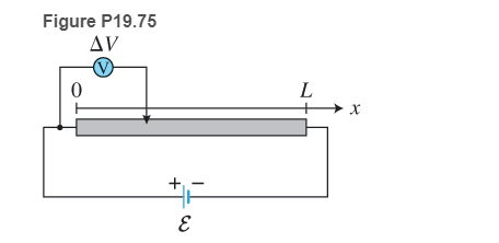
* A nickel wire of length L and a voltmeter are connected to a battery as shown in Figure P19.75. One terminal of the voltmeter is connected to the left end of the nickel wire and the other terminal can slide along the wire. The battery has negligible internal resistance and an emf
Want to see the full answer?
Check out a sample textbook solution
Chapter 19 Solutions
College Physics
Additional Science Textbook Solutions
University Physics Volume 2
University Physics (14th Edition)
University Physics with Modern Physics (14th Edition)
Applied Physics (11th Edition)
Essential University Physics: Volume 1 (3rd Edition)
Physics: Principles with Applications


- In Figure P29.81, N real batteries, each with an emf and internal resistance r, are connected in a closed ring. A resistor R can be connected across any two points of this ring, causing there to be n real batteries in one branch and N n resistors in the other branch. Find an expression for the current through the resistor R in this case.arrow_forwardAn ideal emf device is connected to a set of resistors as shown in Figure P29.66. Find an expression for the current through the resistor R3 in terms of the emf and the resistances.arrow_forwardThree 100- resistors are connected as shown in Figure P21.41 The maximum power that can safely be delivered to any one resistor is 25.0 W. (a) What is the maximum potential difference that can be applied to the terminals a and b? (b) For the voltage determined in part (a), what is the power delivered to each resistor? (c) What is the total power delivered to the combination of resistors?arrow_forward
- An automobile starter motor has an equivalent resistance of 0.0500 and is supplied by a 12.0-V battery with a 0.0100- internal resistance, (a) What is thecurrent to the motor? (b) What voltage is applied to it? (c) What power is supplied to the motor? (d) Repeat these calculations for when the battery connections are corroded and add 0.0900 to the circuit. (Significant problems are caused by even small amounts of unwanted resistance in low-voltage, high-current applications.)arrow_forwardA battery with = 6.00 V and no internal resistance supplies current to the circuit shown in Figure P27.9. When the double-throw switch S is open as shown in the figure, the current in the battery is 1.00 mA. When the switch is closed in position a, the current in the battery is 1.20 mA. When the switch is closed in position b, the current in the battery is 2.00 mA. Find the resistances (a) R1, (b) R2, and (c) R3. Figure P27.9 Problems 9 and 10.arrow_forward(a) Can the circuit shown in Figure P18.29 be reduced to a single resistor connected to the batteries? Explain. (b) Find the magnitude of the current and its direction in each resistor. Figure P18.29arrow_forward
- You have a faculty position at a community college and are m (caching a class in automotive technology. You are deep in a discussion of using jumper cables to start a car with a dead battery from a car with a fresh battery. You have drawn the circuit diagram in Figure P27.16 to explain the process. The battery on the left is the live batten- in the correctly functioning car, with emf and internal resistance RL where the L. subscript refers to live. Its terminals are connected directly across those of the dead battery, in the middle of the diagram, with emf and internal resistance RD where the D subscript refers to "dead Then, the starter in the car with the dead battery is activated by closing the ignition switch, allowing the car to start. The resistance of the starter is Rs. A student raises his hand and asks, So is the dead battery being charged while the starter is operating? How do you respond?arrow_forwardThe circuit shown in Figure P28.78 is set up in the laboratory to measure an unknown capacitance C in series with a resistance R = 10.0 M powered by a battery whose emf is 6.19 V. The data given in the table are the measured voltages across the capacitor as a function of lime, where t = 0 represents the instant at which the switch is thrown to position b. (a) Construct a graph of In (/v) versus I and perform a linear least-squares fit to the data, (b) From the slope of your graph, obtain a value for the time constant of the circuit and a value for the capacitance. v(V) t(s) In (/v) 6.19 0 5.56 4.87 4.93 11.1 4.34 19.4 3.72 30.8 3.09 46.6 2.47 67.3 1.83 102.2arrow_forwardWhen resistors with different resistances are connected in parallel, which of the following must be the same for each resistor? Choose all correct answers, (a) potential difference (b) current (c) power delivered (d) charge entering each resistor in a given time interval (e) none of those answersarrow_forward
- A charge Q is placed on a capacitor of capacitance C. The capacitor is connected into the circuit shown in Figure P26.37, with an open switch, a resistor, and an initially uncharged capacitor of capacitance 3C. The switch is then closed, and the circuit comes to equilibrium. In terms of Q and C, find (a) the final potential difference between the plates of each capacitor, (b) the charge on each capacitor, and (c) the final energy stored in each capacitor. (d) Find the internal energy appearing in the resistor. Figure P26.37arrow_forwardA person with body resistance between his hands of 1.00 k accidentally grasps the terminals of a 20.0-kV power supply. (Do NOT do this!) (a) Draw a circuit diagram to represent the situation. (b) If the internal resistance of the power supply is 2000 , what is the current through his body? (c) What is the power dissipated in his body? (d) If the power supply is to be made safe by increasing its internal resistance, what should the internal resistance be for the maximum current in this situation to be 1.00 mA or less? (e) Will this modification compromise the effectiveness of the power supply for driving low-re si stance devices? Explain your reasoning,arrow_forwardWhy is the following situation impossible? A technician is testing a circuit that contains a resistance R. He realizes that a better design for the circuit would include a resistance 73R rather than R. He has three additional resistors, each with resistance R. By combining these additional resistors in a certain combination that is then placed in series with the original resistor, he achieves the desired resistance.arrow_forward
 Physics for Scientists and Engineers: Foundations...PhysicsISBN:9781133939146Author:Katz, Debora M.Publisher:Cengage Learning
 Principles of Physics: A Calculus-Based TextPhysicsISBN:9781133104261Author:Raymond A. Serway, John W. JewettPublisher:Cengage Learning
 Physics for Scientists and Engineers, Technology ...PhysicsISBN:9781305116399Author:Raymond A. Serway, John W. JewettPublisher:Cengage Learning
 College PhysicsPhysicsISBN:9781938168000Author:Paul Peter Urone, Roger HinrichsPublisher:OpenStax College
 Physics for Scientists and Engineers with Modern ...PhysicsISBN:9781337553292Author:Raymond A. Serway, John W. JewettPublisher:Cengage Learning
 Physics for Scientists and EngineersPhysicsISBN:9781337553278Author:Raymond A. Serway, John W. JewettPublisher:Cengage Learning