Concept explainers
Videos
Three light sources (a lightbulb, a blue LED
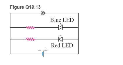
a. The blue LED
b. The red LED
c. The lightbulb
d. Both the blue LED and the red LED
e. All light sources will glow.
Want to see the full answer?
Check out a sample textbook solution
Chapter 19 Solutions
College Physics
Additional Science Textbook Solutions
University Physics Volume 2
Physics for Scientists and Engineers: A Strategic Approach with Modern Physics (4th Edition)
Sears And Zemansky's University Physics With Modern Physics
Introduction to Electrodynamics
University Physics with Modern Physics (14th Edition)
The Cosmic Perspective Fundamentals (2nd Edition)


- The circuit in Figure P27.35 has been connected for several seconds. Find the current (a) in the 4.00-V battery, (b) in the 3.00- resistor, (c) in the 8.00-V battery, and (d) in the 3.00-V battery. (e) Find the charge on the capacitor. Figure P27.35arrow_forwardFigure P18.26 shows a voltage divider, a circuit used to obtain a desired voltage Vout from a source voltage . Determine the required value of R2 if = 5.00 V, Vout = 1.50 V and R1 = 1.00 103 (Hint: Use Kirchhoff's loop rule, substituting Vout = IR2, to find the current. Then solve Ohms law for R2. Figure P18.26arrow_forwardThe circuit shown in Figure P28.78 is set up in the laboratory to measure an unknown capacitance C in series with a resistance R = 10.0 M powered by a battery whose emf is 6.19 V. The data given in the table are the measured voltages across the capacitor as a function of lime, where t = 0 represents the instant at which the switch is thrown to position b. (a) Construct a graph of In (/v) versus I and perform a linear least-squares fit to the data, (b) From the slope of your graph, obtain a value for the time constant of the circuit and a value for the capacitance. v(V) t(s) In (/v) 6.19 0 5.56 4.87 4.93 11.1 4.34 19.4 3.72 30.8 3.09 46.6 2.47 67.3 1.83 102.2arrow_forward
- Electric current I enters a node with three resistors connected in parallel (Fig. CQ18.5). Which one of the following is correct? (a) I1 = I and I2 = I3 = 0. (b) I2 I1 and I2 I3. (c) V1 V2 V3 (d) I1 I2 I3 0. Figure CQ18.5arrow_forwardFor the purpose of measuring the electric resistance of shoes through the body of the wearer standing on a metal ground plate, the American National Standards Institute (ANSI) specifies the circuit shown in Figure P27.14. The potential difference V across the 1.00-M resistor is measured with an ideal voltmeter. (a) Show that the resistance of the footwear is Rshoes=50.0VVV (b) In a medical test, a current through the human body should not exceed 150 A. Can the current delivered by the ANSI-specified circuit exceed 150 A? To decide, consider a person standing barefoot on the ground plate. Figure P27.14arrow_forwardThe circuit in Figure P27.34a consists of three resistors and one battery with no internal resistance. (a) Find the current in the 5.00- resistor. (b) Find the power delivered to the 5.00- resistor. (c) In each of the circuits in Figures P27.34b, P27.34c, and P27.34d, an additional 15.0-V battery has been inserted into the circuit. Which diagram or diagrams represent a circuit that requires the use of Kirchhoffs rules to find the currents? Explain why. (d) In which of these three new circuits is the smallest amount of power delivered to the 10.0- resistor? (You need not calculate the power in each circuit if you explain your answer.) Figure P27.34arrow_forward
- A battery with = 6.00 V and no internal resistance supplies current to the circuit shown in Figure P27.9. When the double-throw switch S is open as shown in the figure, the current in the battery is 1.00 mA. When the switch is closed in position a, the current in the battery is 1.20 mA. When the switch is closed in position b, the current in the battery is 2.00 mA. Find the resistances (a) R1, (b) R2, and (c) R3. Figure P27.9 Problems 9 and 10.arrow_forward(a) What is the average power output of a heart defibrillator that dissipates 400 J of energy in 10.0 ms? (b) Considering the high-power output, why doesn’t the defibrillator produce serious bums?arrow_forwardA charge Q is placed on a capacitor of capacitance C. The capacitor is connected into the circuit shown in Figure P26.37, with an open switch, a resistor, and an initially uncharged capacitor of capacitance 3C. The switch is then closed, and the circuit comes to equilibrium. In terms of Q and C, find (a) the final potential difference between the plates of each capacitor, (b) the charge on each capacitor, and (c) the final energy stored in each capacitor. (d) Find the internal energy appearing in the resistor. Figure P26.37arrow_forward
- Two 1.5-V batteries are required in a flashlight. a. If the batteries are connected as shown in configuration 1 in Figure P27.18, what is the potential difference between points A and B? b. If, instead, the batteries are connected as shown in configuration 2, what is the potential difference between points A and B? c. Use your answers to figure out why a flashlight with two good batteries may not light up. FIGURE P27.18arrow_forwardFour resistors are connected to a battery as shown in Figure P21.40. The current in the battery is I, the battery emf is , and the resistor values are R1 = R, R2 = 2R, R3 = 4R, and R4 = 3R. (a) Rank the resistors according to the potential difference across them, from largest to smallest. Note any cases of equal potential differences. (b) Determine the potential difference across each resistor in terms of . (c) Rank the resistors according to the current in them, from largest to smallest. Note any cases of equal currents. (d) Determine the current in each resistor in terms of I. (e) If R3 is increased, what happens to the current in each of the resistors? (f) In the limit that R3 , what are the new values of the current in each resistor in terms of I, the original current in the battery? Figure P21.40arrow_forwardConsider the circuit below. The capacitor has a capacitance of 10 mF. The switch is closed and after a long time the capacitor is fully charged, (a) What is the current through each resistor a long time after the switch is closed? (b) What is the voltage across each resistor a long rime after the switch is closed? (c) What is the voltage across the capacitor a long time after the switch is closed? (d) What is the charge on the capacitor a long time after the switch is closed? (e) The switch is then opened. The capacitor discharges through the resistors. How long from the time before the current drops to one fifth of the initial value?arrow_forward
 Physics for Scientists and Engineers with Modern ...PhysicsISBN:9781337553292Author:Raymond A. Serway, John W. JewettPublisher:Cengage Learning
 Physics for Scientists and Engineers, Technology ...PhysicsISBN:9781305116399Author:Raymond A. Serway, John W. JewettPublisher:Cengage Learning
 Physics for Scientists and Engineers: Foundations...PhysicsISBN:9781133939146Author:Katz, Debora M.Publisher:Cengage Learning
 College PhysicsPhysicsISBN:9781305952300Author:Raymond A. Serway, Chris VuillePublisher:Cengage Learning
 Physics for Scientists and EngineersPhysicsISBN:9781337553278Author:Raymond A. Serway, John W. JewettPublisher:Cengage Learning