Loose Leaf For Design Of Machinery (mcgraw-hill Series In Mechanical Engineering)
6th Edition
ISBN: 9781260431308
Author: Robert L. Norton
Publisher: McGraw-Hill Education
expand_more
expand_more
format_list_bulleted
Concept explainers
Videos
Textbook Question
Chapter 2, Problem 2.64P
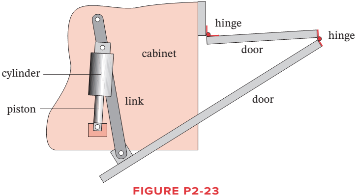
Figure P2-23 shows the top view of the partially open doors on one side of an entertainment center cabinet. The wooden doors are hinged to each other and one door is hinged to the cabinet. There is also a ternary, metal link attached to the cabinet and
Expert Solution & Answer
Want to see the full answer?
Check out a sample textbook solution
Students have asked these similar questions
The second picture has the side view while the first picture has the top view
Inclined plane diagram:
Also String 1
String 2
String 1
B
C
A
The diagram above shows Carts B and C which roll without friction over an inclined plane. The plane is inclined at an angle of theta = 0 away from vertical, as
shown in the diagram. Carts B and C are connected by an essentially massless string. Another massless string runs from Cart B over a massless and frictionless
pulley to a hanging block, Block A.
Q2:
For mechanical system shown in Figure construct the equivalent Grounded-Chair
Representation and determine equations relate f and x, f and y, x and y.Then represent the
associated block diagram.
B2
K2 y
B
K,
B1
M
Activate Wi
Go to Settings
K1
WWWW
Chapter 2 Solutions
Loose Leaf For Design Of Machinery (mcgraw-hill Series In Mechanical Engineering)
Ch. 2 - Find three (or other number as assigned) of the...Ch. 2 - How many DOF do you have in your wrist and hand...Ch. 2 - How many DOF do the following joints have? Your...Ch. 2 - How many DOF do the following have in their normal...Ch. 2 - Are the joints in Problem 2-3 force closed or form...Ch. 2 - Describe the motion of the following items as pure...Ch. 2 - Calculate the mobility of the linkages assigned...Ch. 2 - Identify the items in Figure P2-1 as mechanisms,...Ch. 2 - Use linkage transformation on the linkage of...Ch. 2 - Prob. 2.10P
Ch. 2 - Use number synthesis to find all the possible link...Ch. 2 - Prob. 2.12PCh. 2 - Use linkage transformation to create a 1-DOF...Ch. 2 - Use linkage transformation to create a 1-DOF...Ch. 2 - Calculate the Grashof condition of the fourbar...Ch. 2 - Prob. 2.16PCh. 2 - Describe the difference between a cam-follower...Ch. 2 - Examine an automobile hood hinge mechanism of the...Ch. 2 - Find an adjustable arm desk lamp of the type shown...Ch. 2 - The torque-speed curve for a 1/8 hp permanent...Ch. 2 - Find the mobility of the mechanisms in Figure...Ch. 2 - Find the Grashof condition and Barker...Ch. 2 - Find the rotatability of each loop of the...Ch. 2 - Find the mobility of the mechanisms in Figure...Ch. 2 - Find the mobility of the ice tongs in Figure P2-6:...Ch. 2 - Prob. 2.26PCh. 2 - Prob. 2.27PCh. 2 - Find the mobility of the corkscrew in Figure P2-9.Ch. 2 - Figure P2-10 shows Watts sun and planet drive that...Ch. 2 - Figure P2-11 shows a bicycle handbrake lever...Ch. 2 - Figure P2-12 shows a bicycle brake caliper...Ch. 2 - Find the mobility, the Grashof condition, and the...Ch. 2 - The approximate torque-speed curve and its...Ch. 2 - Prob. 2.34PCh. 2 - Prob. 2.35PCh. 2 - Sketch the equivalent linkage for the cam and...Ch. 2 - Describe the motion of the following rides,...Ch. 2 - For the mechanism in Figure P2-1 a, number the...Ch. 2 - Repeat Problem 2-38 for Figure P2-1b.Ch. 2 - Repeat Problem 2-38 for Figure P2-1c.Ch. 2 - Prob. 2.41PCh. 2 - Find the mobility, the Grashof condition, and the...Ch. 2 - Find the mobility, the Grashof condition, and the...Ch. 2 - Figure P2-20 shows a Rube Goldberg mechanism that...Ch. 2 - All the eightbar linkages in Figure 2-11 part 2...Ch. 2 - Prob. 2.46PCh. 2 - Prob. 2.47PCh. 2 - Find the mobility of the mechanism shown in Figure...Ch. 2 - Find the mobility of the mechanism shown in Figure...Ch. 2 - Find the mobility of the mechanism shown in Figure...Ch. 2 - Find the mobility of the mechanism shown in Figure...Ch. 2 - Prob. 2.52PCh. 2 - Prob. 2.53PCh. 2 - Repeat Problem 2-38 for Figure P2-1f.Ch. 2 - Repeat Problem 2-38 for Figure P2-1g.Ch. 2 - For the example linkage shown in Figure 2-4 find...Ch. 2 - For the linkage shown in Figure 2-5b find the...Ch. 2 - Prob. 2.58PCh. 2 - Figure P2-21b shows a mechanism. Find its mobility...Ch. 2 - Prob. 2.60PCh. 2 - Figure P2-21 d shows a log transporter. Draw a...Ch. 2 - Figure P2-21e shows a plow mechanism attached to a...Ch. 2 - Figure P2-22 shows a Hart inversor sixbar linkage....Ch. 2 - Figure P2-23 shows the top view of the partially...Ch. 2 - Figure P2-24a shows the seat and seat-back of a...Ch. 2 - Figure P2-24b shows the mechanism used to extend...Ch. 2 - Figure P2-24b shows the mechanism used to extend...Ch. 2 - Figure P2-25 shows a sixbar linkage. Is it a Watt...Ch. 2 - Use number synthesis o find all the possible link...Ch. 2 - Use number synthesis to find all the possible link...Ch. 2 - Prob. 2.71PCh. 2 - For the mechanism in Figure P2-26, number the...Ch. 2 - Figure P2-27 shows a schematic of an exercise...Ch. 2 - Calculate the mobility of the linkage in Figure...Ch. 2 - Calculate the Grashof condition of the fourbar...Ch. 2 - The drum brake mechanism in Figure P2-4g is a...
Knowledge Booster


Learn more about
Need a deep-dive on the concept behind this application? Look no further. Learn more about this topic, mechanical-engineering and related others by exploring similar questions and additional content below.Similar questions
- For the following figure, draw a kinematic diagram for each identifyingthe point of interest. From there, calculate the mobility of the device.arrow_forwardThe sequence in Figure P2.2 represents a ball rolling into a walland bouncing off of it. The ball is 10 mm in diameter. Make agraph showing the distance from the leading edge of the ballto the closest part of the wall (using the wall as the origin) asit changes from frame to frame.arrow_forwardConsider the system shown in FIGURE P3-44 of the textbook. The designer has made several changes to the system. These changes are: • the load of 6 kN/m has been changed to 11 kN/m, • the central length of 2 m has been changed to 4 m o this means the load is applied over the beam from 1 m to the right of point 'A' TO point 'C'. What is the magnitude of the resultant of the distributed load? O 5 kN O 55 kN O 0.513 kN O 93.6 kN O 11 kN O 12.1 kN O 91.4 kN O O kNarrow_forward
- Figure Q2-2 shows a schematic of a retractable landing gear of aircraft. The retraction mechanism is a 4 bar linkage (O1ABO2), which is actuated by a hydraulic cylinder and piston, D, pivoted at E with a joint at C to link O,A. Hydraulic cylinder & piston D Joint for landing gear wheel Figure Q2-2 Use the Gruebler's equation of DoF (Degrees of Freedom) of a linkage mechanism to assess if the landing gear produces the required retraction motion. 0,02 may be considered as the ground link. i) Hint: The joint of the wheel is not part of the linkage mechanism. The number of DoF may be used to check if it is a linkage with certain motions or a fixed structure. ii) The dimensions of the 4 bar linkage (O1ABO2) are measured as O102 = 800 mm, O1A = 780 mm, AB = 200 mm and O2B = 400 mm. Use Grashof condition to determine the specific type of this linkage. You may find the Gruebler's equation useful: M = 3(L – 1) – 2J where, M is degree of freedom (DoF) L is number of links J is number of jointsarrow_forwardFind the RPR Diagram of 2 dof robotic arm and calculate DOF valuearrow_forwardPls help me with my plates Block 4 slides in the slot in the fixed piece 1. Axis Q2 of crank 2 is fixed on 1. Q2A = 1.5 inches, and AB = 4.5 inches. Draw the mechanism, assuming dimensions for 1, if desired or use center lines only. Draw the four-bar linkage for this mechanism, properly rotate the linkage Q2ABQ4∞, name each link, and show the finite infinite cranks.arrow_forward
- 1–2. Figure C1.2 shows a mechanism that is typical in the tank of a water closet. Note that flapper C is hollow and filled with trapped air. Carefully examine the configuration of the components in the mechanism. Then answer the following leading questions to gain insight into the operation of the mechanism. 1. As the handle A is rotated counterclockwise, what is the motion of flapper C? 2. When flapper C is raised, what effect is seen? 3. When flapper C is lifted, it tends to remain in an upward position for a period of time. What causes this tendency to keep the flapper lifted? 4. When will this tendency (to keep flapper C lifted) cease Plz connect me if you want to explan subject for me .... +962 79180149 Thxarrow_forwardGiven the two-link planar arm with rotary joints below. For this arm, the second link is half as long as the first–that is, L1 = 2L2. The joint range limits in degrees are: 0 < 0, < 180, -90 < 02 < 180. L1 Sketch the approximate reachable workspace (an area) of the tip of link 2.arrow_forwardSlide B travels along the center line XX'. Q2A = 18 cm, AB = 72 cm. 1. With the crank in the position shown, draw the four bar linkage. Name each link and show the finite and infinite cranks.2. Find the two extreme positions of block B. Express your answer in terms of the acute angle formed by crank Q2A with the horizontal axis (like the angle 45° in the figure)3. Determine the length of the stroke of B. Write your answer in two decimal places.arrow_forward
- Topics Discussed: Dynamics of Rigid Bodies, Position Vector, Force Vector Direction, Cartesian Vector, etc. Kindly show the complete solution. Also show the free-body diagram/illustration diagram. Please make sure that your handwriting is understandable and the picture of the solution is clear. I will rate you with “like/upvote” after. I need the answer right away, thank you.arrow_forwardMFG 232: Åpplied Statics LAB 8A : Moment ota Force 3-6 Calculate the moment about point A in Figure P3-6. 800 lb 200 lb 400 lb -7' 3- Figure P3-6arrow_forwardConsider the system shown in FIGURE P3-44 of the textbook. The designer has made several changes to the system. These changes are: the load of 6 kN/m has been changed to 11 kN/m, the central length of 2 m has been changed to 4 m o this means the load is applied over the beam from 1 m to the right of point 'A' TO point 'C'. What is the direction of the resultant of the distributed load? 0° 90° 180° 270°arrow_forward
arrow_back_ios
SEE MORE QUESTIONS
arrow_forward_ios
Recommended textbooks for you
 Elements Of ElectromagneticsMechanical EngineeringISBN:9780190698614Author:Sadiku, Matthew N. O.Publisher:Oxford University Press
 Mechanics of Materials (10th Edition)Mechanical EngineeringISBN:9780134319650Author:Russell C. HibbelerPublisher:PEARSON
 Thermodynamics: An Engineering ApproachMechanical EngineeringISBN:9781259822674Author:Yunus A. Cengel Dr., Michael A. BolesPublisher:McGraw-Hill Education
 Control Systems EngineeringMechanical EngineeringISBN:9781118170519Author:Norman S. NisePublisher:WILEY
 Mechanics of Materials (MindTap Course List)Mechanical EngineeringISBN:9781337093347Author:Barry J. Goodno, James M. GerePublisher:Cengage Learning
 Engineering Mechanics: StaticsMechanical EngineeringISBN:9781118807330Author:James L. Meriam, L. G. Kraige, J. N. BoltonPublisher:WILEY
Elements Of Electromagnetics
Mechanical Engineering
ISBN:9780190698614
Author:Sadiku, Matthew N. O.
Publisher:Oxford University Press
Mechanics of Materials (10th Edition)
Mechanical Engineering
ISBN:9780134319650
Author:Russell C. Hibbeler
Publisher:PEARSON
Thermodynamics: An Engineering Approach
Mechanical Engineering
ISBN:9781259822674
Author:Yunus A. Cengel Dr., Michael A. Boles
Publisher:McGraw-Hill Education
Control Systems Engineering
Mechanical Engineering
ISBN:9781118170519
Author:Norman S. Nise
Publisher:WILEY
Mechanics of Materials (MindTap Course List)
Mechanical Engineering
ISBN:9781337093347
Author:Barry J. Goodno, James M. Gere
Publisher:Cengage Learning
Engineering Mechanics: Statics
Mechanical Engineering
ISBN:9781118807330
Author:James L. Meriam, L. G. Kraige, J. N. Bolton
Publisher:WILEY
Force | Free Body Diagrams | Physics | Don't Memorise; Author: Don't Memorise;https://www.youtube.com/watch?v=4Bwwq1munB0;License: Standard YouTube License, CC-BY