
DESIGN OF MACHINERY
6th Edition
ISBN: 9781260113310
Author: Norton
Publisher: RENT MCG
expand_more
expand_more
format_list_bulleted
Videos
Textbook Question
Chapter 2, Problem 2.66P
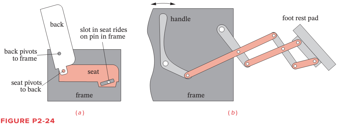
Figure P2-24b shows the mechanism used to extend the foot support on a reclining chair. Draw its kinematic diagram and determine its mobility with respect to the frame of the chair.
Expert Solution & Answer
Want to see the full answer?
Check out a sample textbook solution
Students have asked these similar questions
For the walking-beam mechanism of Figure P4-9, calculate and plot the xand y components of the position of the coupler point P for one complete revolution of the crank O2A. Hint: Calculate them first with respect to the ground link O204 and then transform them into the global XY coordinate system (i.e., horizontal and vertical in the figure). Scale the figure for any additional information needed
Figure p3-31 the only problem I want to sol
Determine the degrees of freedom by constructing the mechanisms belonging to the given kinematic chain.
Chapter 2 Solutions
DESIGN OF MACHINERY
Ch. 2 - Find three (or other number as assigned) of the...Ch. 2 - How many DOF do you have in your wrist and hand...Ch. 2 - How many DOF do the following joints have? Your...Ch. 2 - How many DOF do the following have in their normal...Ch. 2 - Are the joints in Problem 2-3 force closed or form...Ch. 2 - Describe the motion of the following items as pure...Ch. 2 - Calculate the mobility of the linkages assigned...Ch. 2 - Identify the items in Figure P2-1 as mechanisms,...Ch. 2 - Use linkage transformation on the linkage of...Ch. 2 - Prob. 2.10P
Ch. 2 - Use number synthesis to find all the possible link...Ch. 2 - Prob. 2.12PCh. 2 - Use linkage transformation to create a 1-DOF...Ch. 2 - Use linkage transformation to create a 1-DOF...Ch. 2 - Calculate the Grashof condition of the fourbar...Ch. 2 - Prob. 2.16PCh. 2 - Describe the difference between a cam-follower...Ch. 2 - Examine an automobile hood hinge mechanism of the...Ch. 2 - Find an adjustable arm desk lamp of the type shown...Ch. 2 - The torque-speed curve for a 1/8 hp permanent...Ch. 2 - Find the mobility of the mechanisms in Figure...Ch. 2 - Find the Grashof condition and Barker...Ch. 2 - Find the rotatability of each loop of the...Ch. 2 - Find the mobility of the mechanisms in Figure...Ch. 2 - Find the mobility of the ice tongs in Figure P2-6:...Ch. 2 - Prob. 2.26PCh. 2 - Prob. 2.27PCh. 2 - Find the mobility of the corkscrew in Figure P2-9.Ch. 2 - Figure P2-10 shows Watts sun and planet drive that...Ch. 2 - Figure P2-11 shows a bicycle handbrake lever...Ch. 2 - Figure P2-12 shows a bicycle brake caliper...Ch. 2 - Find the mobility, the Grashof condition, and the...Ch. 2 - The approximate torque-speed curve and its...Ch. 2 - Prob. 2.34PCh. 2 - Prob. 2.35PCh. 2 - Sketch the equivalent linkage for the cam and...Ch. 2 - Describe the motion of the following rides,...Ch. 2 - For the mechanism in Figure P2-1 a, number the...Ch. 2 - Repeat Problem 2-38 for Figure P2-1b.Ch. 2 - Repeat Problem 2-38 for Figure P2-1c.Ch. 2 - Prob. 2.41PCh. 2 - Find the mobility, the Grashof condition, and the...Ch. 2 - Find the mobility, the Grashof condition, and the...Ch. 2 - Figure P2-20 shows a Rube Goldberg mechanism that...Ch. 2 - All the eightbar linkages in Figure 2-11 part 2...Ch. 2 - Prob. 2.46PCh. 2 - Prob. 2.47PCh. 2 - Find the mobility of the mechanism shown in Figure...Ch. 2 - Find the mobility of the mechanism shown in Figure...Ch. 2 - Find the mobility of the mechanism shown in Figure...Ch. 2 - Find the mobility of the mechanism shown in Figure...Ch. 2 - Prob. 2.52PCh. 2 - Prob. 2.53PCh. 2 - Repeat Problem 2-38 for Figure P2-1f.Ch. 2 - Repeat Problem 2-38 for Figure P2-1g.Ch. 2 - For the example linkage shown in Figure 2-4 find...Ch. 2 - For the linkage shown in Figure 2-5b find the...Ch. 2 - Prob. 2.58PCh. 2 - Figure P2-21b shows a mechanism. Find its mobility...Ch. 2 - Prob. 2.60PCh. 2 - Figure P2-21 d shows a log transporter. Draw a...Ch. 2 - Figure P2-21e shows a plow mechanism attached to a...Ch. 2 - Figure P2-22 shows a Hart inversor sixbar linkage....Ch. 2 - Figure P2-23 shows the top view of the partially...Ch. 2 - Figure P2-24a shows the seat and seat-back of a...Ch. 2 - Figure P2-24b shows the mechanism used to extend...Ch. 2 - Figure P2-24b shows the mechanism used to extend...Ch. 2 - Figure P2-25 shows a sixbar linkage. Is it a Watt...Ch. 2 - Use number synthesis o find all the possible link...Ch. 2 - Use number synthesis to find all the possible link...Ch. 2 - Prob. 2.71PCh. 2 - For the mechanism in Figure P2-26, number the...Ch. 2 - Figure P2-27 shows a schematic of an exercise...Ch. 2 - Calculate the mobility of the linkage in Figure...Ch. 2 - Calculate the Grashof condition of the fourbar...Ch. 2 - The drum brake mechanism in Figure P2-4g is a...
Knowledge Booster


Learn more about
Need a deep-dive on the concept behind this application? Look no further. Learn more about this topic, mechanical-engineering and related others by exploring similar questions and additional content below.Similar questions
- Draw the Kinematic Diagram of the following Mechanism (label the links andjoints). Then, calculate their Degree of Freedom.arrow_forwardGiven: AB = 0.1 m , CB = 0.4 m, CD = 0.6 m, AD = 0.8 m For the linkage shown below, CD moves back and forth spinning flywheel AB, link CD is the input link. a.) Find the maximum angle in degrees, that is the angle between the extreme positions by the link CD when the circle AB rotates 360 degrees? b.) Why is the wheel able to rotate fully and not get locked up when CD and AB are inline (collinear)? Where's a real life example where this mechanism may be used?arrow_forwardDraw the kinematic diagram of the following mechanismarrow_forward
- The kinematic scheme of the mechanism is given. Point C is the center of curvature of the link 3 at the point of the contact. Link 2 is with circular shape with center point B. Find the degrees of freedom.arrow_forwardThe linkage Q₂BCDEQ₄KF represents the mechanism of the Corliss non-releasing valve gear. Q₂B is a crank 3⅛- inches long oscillating to the right of fixed center Q₂. Q₂C is another crank which is 3⅜-inches long and oscillates below Q₂. Q₄ is a fixed center on a horizontal line through Q₂ and 6 -inches to right of Q₂. EQ₄K to right of Q₄E. Q₄E = 3⅝- inches and Q₄K = 5 -inches. CE is a connecting rod 3½-inches long. BD is a link 2 - inches long connecting B to link CE at D, 1 -inch. from C. KF is a connecting link 8- inches long extending to right of K and is attached to a slide block at F which moves on a horizontal line parallel to and 3-inches below Q₂Q₄. When F, moving to left, reaches a position such that K is to the left of Q₄, and Q₄K makes an angle of 15º to left of vertical, it has a velocity of 5 fps. 1.1 Draw and label the mechanism of the Corliss non-releasing valve gear. 1.2 Find the velocity K in feet per second 1.3 Find the velocity of E in feet per second 1.4 Find the…arrow_forwardFigure P-1134 represents a schematic diagram of a Porter governor. Eachflyball weighs 16.1 lb and central weight D is 40 lb. Determine the rotationalspeed in rpm about the vertical axis AD at which the weight D begins to rise.arrow_forward
- Draw the kinematic diagram of the given mechanism below. Calculate its mobility as well in terms of the number of degrees offreedom. In addition to this, determine and locate all instant centers of the given mechanism on the kinematic diagram that will becreated.arrow_forwardDraw the kinematic diagrams of the following mechanisms and compute the number of Degreesof Freedom (Mobility)arrow_forwardProblem 2 The linkage in Figure P7-5b has o4A = o2A = 0.75, AB = 1.5, and AC = 1.2 in. The effective crank angle in the position shown is 77° and angle BAC = 30°. Find a3, AA, AB, Ac for the position shown for w2 = 15 rad/sec and a2 = 10 rad/sec^2 in the directions shown using an analytic method. (Hint: Create an effective linkage for the position shown and analyze it as a pin-jointed fourbar.) the linkage has a parallelogram form Assume rolling contactarrow_forward
- Sketch the kinematic diagram and calculate the mobility of all the linkages (Degrees of Freedom). Are there any assumptions if any.arrow_forwardPlease Solve Q4 with sketch T-S diagramarrow_forwardPls help me with my plates Block 4 slides in the slot in the fixed piece 1. Axis Q2 of crank 2 is fixed on 1. Q2A = 1.5 inches, and AB = 4.5 inches. Draw the mechanism, assuming dimensions for 1, if desired or use center lines only. Draw the four-bar linkage for this mechanism, properly rotate the linkage Q2ABQ4∞, name each link, and show the finite infinite cranks.arrow_forward
arrow_back_ios
SEE MORE QUESTIONS
arrow_forward_ios
Recommended textbooks for you
 Elements Of ElectromagneticsMechanical EngineeringISBN:9780190698614Author:Sadiku, Matthew N. O.Publisher:Oxford University Press
 Mechanics of Materials (10th Edition)Mechanical EngineeringISBN:9780134319650Author:Russell C. HibbelerPublisher:PEARSON
 Thermodynamics: An Engineering ApproachMechanical EngineeringISBN:9781259822674Author:Yunus A. Cengel Dr., Michael A. BolesPublisher:McGraw-Hill Education
 Control Systems EngineeringMechanical EngineeringISBN:9781118170519Author:Norman S. NisePublisher:WILEY
 Mechanics of Materials (MindTap Course List)Mechanical EngineeringISBN:9781337093347Author:Barry J. Goodno, James M. GerePublisher:Cengage Learning
 Engineering Mechanics: StaticsMechanical EngineeringISBN:9781118807330Author:James L. Meriam, L. G. Kraige, J. N. BoltonPublisher:WILEY
Elements Of Electromagnetics
Mechanical Engineering
ISBN:9780190698614
Author:Sadiku, Matthew N. O.
Publisher:Oxford University Press
Mechanics of Materials (10th Edition)
Mechanical Engineering
ISBN:9780134319650
Author:Russell C. Hibbeler
Publisher:PEARSON
Thermodynamics: An Engineering Approach
Mechanical Engineering
ISBN:9781259822674
Author:Yunus A. Cengel Dr., Michael A. Boles
Publisher:McGraw-Hill Education
Control Systems Engineering
Mechanical Engineering
ISBN:9781118170519
Author:Norman S. Nise
Publisher:WILEY
Mechanics of Materials (MindTap Course List)
Mechanical Engineering
ISBN:9781337093347
Author:Barry J. Goodno, James M. Gere
Publisher:Cengage Learning
Engineering Mechanics: Statics
Mechanical Engineering
ISBN:9781118807330
Author:James L. Meriam, L. G. Kraige, J. N. Bolton
Publisher:WILEY
Polymer Basics; Author: Tonya Coffey;https://www.youtube.com/watch?v=c5gFHpWvDXk;License: Standard youtube license