Understanding Motor Controls
3rd Edition
ISBN: 9781305498129
Author: Stephen L. Herman
Publisher: Cengage Learning
expand_more
expand_more
format_list_bulleted
Videos
Textbook Question
Chapter 2, Problem 5RQ
The symbol shown is:
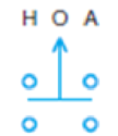
- a. Double acting push button
- b. Two-position selector switch
- c. Three-position selector switch
- d. Maintained contact push button
Expert Solution & Answer
Want to see the full answer?
Check out a sample textbook solution
Students have asked these similar questions
Describe one of control section component which is used to operate double acting cylinder of having 3 position and 4 ports with the electrical, mechanical and manual method of actuation.
Define relay
please explain for c) what is Sum of M at hinge
Chapter 2 Solutions
Understanding Motor Controls
Ch. 2 - Prob. 1RQCh. 2 - The symbol shown is:
Normally closed float...Ch. 2 - The symbol shown is: a. Iron core transformer b....Ch. 2 - The symbol shown is:
Normally open pressure...Ch. 2 - The symbol shown is: a. Double acting push button...Ch. 2 - If you were installing the circuit in Figure 233,...Ch. 2 - Referring to the circuit in Figure 2–33, should...Ch. 2 - Prob. 8RQCh. 2 - Prob. 9RQCh. 2 - When reading a schematic diagram, are the control...
Knowledge Booster


Learn more about
Need a deep-dive on the concept behind this application? Look no further. Learn more about this topic, mechanical-engineering and related others by exploring similar questions and additional content below.Similar questions
- when the bottom of a control arm is toward the front of the car and the point turns in to meet the upright, it is called a ?arrow_forwardFOR A FANUC 6 axis robot What is the purpose of the Deadman’s switch?arrow_forwardThe symbol shown is: Normally open pressure switch Normally open flow switch Normally open float switch Normally open temperature switcharrow_forward
- Refer to Figure 21–1 to answer the following questions. In what position must switch SW 123 be set to make connection between terminals 3 and 4?arrow_forwardWhen reading a schematic diagram, are the control components shown as they should be when the machine is turned off or de-energized, or are they shown as they should be when the machine is in operation?arrow_forwardWhat is a normally dosed switch?arrow_forward
arrow_back_ios
arrow_forward_ios
Recommended textbooks for you
 Understanding Motor ControlsMechanical EngineeringISBN:9781337798686Author:Stephen L. HermanPublisher:Delmar Cengage Learning
 Refrigeration and Air Conditioning Technology (Mi...Mechanical EngineeringISBN:9781305578296Author:John Tomczyk, Eugene Silberstein, Bill Whitman, Bill JohnsonPublisher:Cengage Learning
 Automotive Technology: A Systems Approach (MindTa...Mechanical EngineeringISBN:9781133612315Author:Jack Erjavec, Rob ThompsonPublisher:Cengage Learning
Understanding Motor Controls
Mechanical Engineering
ISBN:9781337798686
Author:Stephen L. Herman
Publisher:Delmar Cengage Learning
Refrigeration and Air Conditioning Technology (Mi...
Mechanical Engineering
ISBN:9781305578296
Author:John Tomczyk, Eugene Silberstein, Bill Whitman, Bill Johnson
Publisher:Cengage Learning
Automotive Technology: A Systems Approach (MindTa...
Mechanical Engineering
ISBN:9781133612315
Author:Jack Erjavec, Rob Thompson
Publisher:Cengage Learning
The Refrigeration Cycle Explained - The Four Major Components; Author: HVAC Know It All;https://www.youtube.com/watch?v=zfciSvOZDUY;License: Standard YouTube License, CC-BY