
Introductory Circuit Analysis (13th Edition)
13th Edition
ISBN: 9780133923605
Author: Robert L. Boylestad
Publisher: PEARSON
expand_more
expand_more
format_list_bulleted
Videos
Textbook Question
Chapter 20, Problem 14P
For the system of Fig. 20.59:
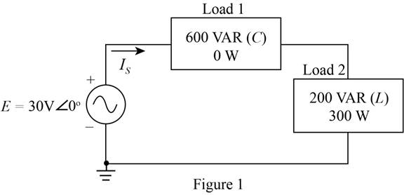
a. Find the total number of watts. volt-amperes reactive, volt-amperes, and Fp.
b. Find the current ls.
c. Draw the power triangle.
d. Find the type of elements and their impedance in ohms within each electrical box. (Assume that all elements of a load are in series.)
e. Verity that the result of part (b) is correct by finding the current ls using only the input voltage E and the results of part (d). Compare the value of ls with that obtained for part (b).
Expert Solution & Answer
Want to see the full answer?
Check out a sample textbook solution
Students have asked these similar questions
For the circuit shown,a) To the coil of a henry, measure its internal resistance and the value of the inductance.b) Measure the effective voltage and current at the terminals of the 100 Ω resistor and at the source.c) Measure the average power delivered by the source.Note the phase shift between the supply voltage and the voltage across the 100 Ω resistor (only at this point).
Company Y would like to have a new installation transmission line to open a small new city consist of 300 MW with 0.85 power factor lagging at full load. The new transmission line required 132 kV with 124.274 miles long. All the elements needed for the new transmission line is listed in table shown in the picture. You are required to model the transmission line and analysed the performance of the new transmission lines in terms of voltage regulation and efficiency. Note that the frequency used is 50 Hz.
also given IL=50mA
Chapter 20 Solutions
Introductory Circuit Analysis (13th Edition)
Ch. 20 - For the battery of bulbs (purely resistive)...Ch. 20 - For the network of Fig. 20.49 : a. Find the...Ch. 20 - For the network of Fig. 20.50 : a. Determine the...Ch. 20 - For the system of Fig. 20.51 : a. Find the total...Ch. 20 - For the system of Fig. 20.52 : a. Find PT, QT. and...Ch. 20 - 6. For the system of Fig. 20.53 : a. Find PT, QT....Ch. 20 - For the network of Fig. 20.54 : a. Find the type...Ch. 20 - For the circuit of Fig. 20.55: a. Find the...Ch. 20 - For the network of Fig. 20.56 : a. Find Is. b....Ch. 20 - Repeat Problem 9 for the network of Fig. 20.57.
Ch. 20 - For the network of Fig. 20.58: a. Find the average...Ch. 20 - An electrical system is rated 10 kVA, 200 V at a...Ch. 20 - An electrical system is rated 5 kVA, 120 V, at a...Ch. 20 - For the system of Fig. 20.59: a. Find the total...Ch. 20 - Repeat Problem 14 for the system of Fig. 20.60.Ch. 20 - For the circuit of Fig. 20.61: Find the total...Ch. 20 - For the circuit of Fig. 20.62: Find the total...Ch. 20 - Prob. 18PCh. 20 - The load on a 120 V, 60 Hz supply is 5 kW...Ch. 20 - The loading of a factory on a 1000 V, 60 Hz system...Ch. 20 - a. A wattmeter is connected with its current coil...Ch. 20 - The voltage source in Fig. 20.64 delivers 660 VA...Ch. 20 - a. An air-core coil is connected to a 200 V, 60 Hz...Ch. 20 - a. The inductance of an air-core coil is 0.08 H....Ch. 20 - Using PSpice or Multisim, obtain a plot of...
Knowledge Booster


Learn more about
Need a deep-dive on the concept behind this application? Look no further. Learn more about this topic, electrical-engineering and related others by exploring similar questions and additional content below.Similar questions
- Determine the following: Assume the system is initially relaxedarrow_forwardT:32)arrow_forwarda plant is feeding a load 1.2k feet away. the load demands 100 amps at 500V. an ac system with transformer rated 500/5000V near the generating station and 5000/500V near the load. if the line has resistance of 0.2 ohms and receiving voltage of 500V, find the sending end voltage and powerflows and transmission losses.arrow_forward
- For type-A chopper of fig, dc source voltage is 230 V, load resistance is 10 ohm take a voltage drop of 2 V across chopper when it is on. For duty cycle of 0.4, calculate (A) average and RMS values of output voltage (B) chopper efficiency . please help mearrow_forward21. Which Power Station contributes the least to the overall air pollution? A. GEOTHERMAL POWER PLANTS B. DIESEL POWER PLANTS C. HYDROELECTRIC POWER PLANTS D. COAL-BASED POWER PLANTSarrow_forwarda) To the coil of a henry, measure its internal resistance and the value of the inductance.b) Measure the effective voltage and current at the terminals of the 100 Ω resistor and at the source.c) Measure the average power delivered by the source.Note the phase shift between the supply voltage and the voltage across the 100 Ω resistor (only at this point).arrow_forward
- 1-Alternators can be overloaded by 10 percentage for 10-15 minutes, this a. Steady state voltage stability will get affected b. may reduce the stability limit c. may disturb Nose point d. may lose Angular stability 2-Often, the network is referred as an infinite bus when a change in input mechanical power or in field excitation to the unit does not cause an appreciable change in a. system frequency or terminal voltage b. system frequency alone c. system frequency and terminal voltage d. Total production costarrow_forwardIbc find the load current Vca find the line voltage Calculate the complex power on the transmission linearrow_forwarddetermine Vo, if Vs = 8 cos 1000t V.arrow_forward
- q13/ choose the correct answer The variation of the load is considered over a period of one year in an annual load curve. Select one: True Falsearrow_forwardFor balanced condition, find Q in Maxwell bridge if R1=250Ω, C1=4µF, R2=50Ω, R3=20Ω, f=60Hz .arrow_forwardfind The average power delivered to * .the circuitarrow_forward
arrow_back_ios
SEE MORE QUESTIONS
arrow_forward_ios
Recommended textbooks for you
 Introductory Circuit Analysis (13th Edition)Electrical EngineeringISBN:9780133923605Author:Robert L. BoylestadPublisher:PEARSON
 Delmar's Standard Textbook Of ElectricityElectrical EngineeringISBN:9781337900348Author:Stephen L. HermanPublisher:Cengage Learning
 Programmable Logic ControllersElectrical EngineeringISBN:9780073373843Author:Frank D. PetruzellaPublisher:McGraw-Hill Education
 Fundamentals of Electric CircuitsElectrical EngineeringISBN:9780078028229Author:Charles K Alexander, Matthew SadikuPublisher:McGraw-Hill Education
 Electric Circuits. (11th Edition)Electrical EngineeringISBN:9780134746968Author:James W. Nilsson, Susan RiedelPublisher:PEARSON
 Engineering ElectromagneticsElectrical EngineeringISBN:9780078028151Author:Hayt, William H. (william Hart), Jr, BUCK, John A.Publisher:Mcgraw-hill Education,
Introductory Circuit Analysis (13th Edition)
Electrical Engineering
ISBN:9780133923605
Author:Robert L. Boylestad
Publisher:PEARSON
Delmar's Standard Textbook Of Electricity
Electrical Engineering
ISBN:9781337900348
Author:Stephen L. Herman
Publisher:Cengage Learning
Programmable Logic Controllers
Electrical Engineering
ISBN:9780073373843
Author:Frank D. Petruzella
Publisher:McGraw-Hill Education
Fundamentals of Electric Circuits
Electrical Engineering
ISBN:9780078028229
Author:Charles K Alexander, Matthew Sadiku
Publisher:McGraw-Hill Education
Electric Circuits. (11th Edition)
Electrical Engineering
ISBN:9780134746968
Author:James W. Nilsson, Susan Riedel
Publisher:PEARSON
Engineering Electromagnetics
Electrical Engineering
ISBN:9780078028151
Author:Hayt, William H. (william Hart), Jr, BUCK, John A.
Publisher:Mcgraw-hill Education,
Inductors Explained - The basics how inductors work working principle; Author: The Engineering Mindset;https://www.youtube.com/watch?v=KSylo01n5FY;License: Standard Youtube License