
Introductory Circuit Analysis (13th Edition)
13th Edition
ISBN: 9780133923605
Author: Robert L. Boylestad
Publisher: PEARSON
expand_more
expand_more
format_list_bulleted
Videos
Textbook Question
Chapter 20, Problem 3P
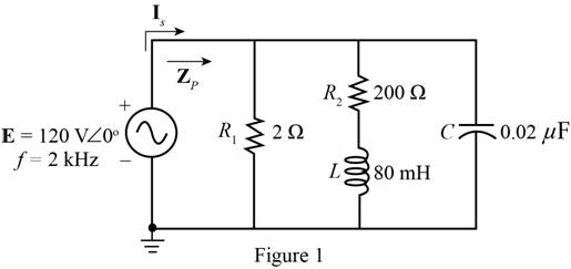
For the network of Fig. 20.50 :
a. Determine the total real, reactive, and apparent power for each parallel branch.
b. Draw the power triangle.
c. Find the total impedance and power factor of the network.
d. Find the source current ls.
Expert Solution & Answer
Want to see the full answer?
Check out a sample textbook solution
Students have asked these similar questions
For the circuit shown,a) To the coil of a henry, measure its internal resistance and the value of the inductance.b) Measure the effective voltage and current at the terminals of the 100 Ω resistor and at the source.c) Measure the average power delivered by the source.Note the phase shift between the supply voltage and the voltage across the 100 Ω resistor (only at this point).
Ibc find the load current
Vca find the line voltage
Calculate the complex power on the transmission line
Find the line and phase voltage if Vcn= 30<50 V. Assuming ACB sequence
Chapter 20 Solutions
Introductory Circuit Analysis (13th Edition)
Ch. 20 - For the battery of bulbs (purely resistive)...Ch. 20 - For the network of Fig. 20.49 : a. Find the...Ch. 20 - For the network of Fig. 20.50 : a. Determine the...Ch. 20 - For the system of Fig. 20.51 : a. Find the total...Ch. 20 - For the system of Fig. 20.52 : a. Find PT, QT. and...Ch. 20 - 6. For the system of Fig. 20.53 : a. Find PT, QT....Ch. 20 - For the network of Fig. 20.54 : a. Find the type...Ch. 20 - For the circuit of Fig. 20.55: a. Find the...Ch. 20 - For the network of Fig. 20.56 : a. Find Is. b....Ch. 20 - Repeat Problem 9 for the network of Fig. 20.57.
Ch. 20 - For the network of Fig. 20.58: a. Find the average...Ch. 20 - An electrical system is rated 10 kVA, 200 V at a...Ch. 20 - An electrical system is rated 5 kVA, 120 V, at a...Ch. 20 - For the system of Fig. 20.59: a. Find the total...Ch. 20 - Repeat Problem 14 for the system of Fig. 20.60.Ch. 20 - For the circuit of Fig. 20.61: Find the total...Ch. 20 - For the circuit of Fig. 20.62: Find the total...Ch. 20 - Prob. 18PCh. 20 - The load on a 120 V, 60 Hz supply is 5 kW...Ch. 20 - The loading of a factory on a 1000 V, 60 Hz system...Ch. 20 - a. A wattmeter is connected with its current coil...Ch. 20 - The voltage source in Fig. 20.64 delivers 660 VA...Ch. 20 - a. An air-core coil is connected to a 200 V, 60 Hz...Ch. 20 - a. The inductance of an air-core coil is 0.08 H....Ch. 20 - Using PSpice or Multisim, obtain a plot of...
Additional Engineering Textbook Solutions
Find more solutions based on key concepts
Design an ideal inverting op-amp circuit such that the voltage gain is Av=25 . The maximum current in any resis...
Microelectronics: Circuit Analysis and Design
Three point charges of equal magnitude q, that will yield a zero net electric field at the origin.
Engineering Electromagnetics
With respect to the circuit in Fig. 5.90, (a) employ Thévenin’s theorem to determine the equivalent network see...
Loose Leaf for Engineering Circuit Analysis Format: Loose-leaf
The voltage source of the circuit shown in Fig. P1.29 is given by s(t)=25cos(4104t45)(V). Obtain an expression ...
Fundamentals of Applied Electromagnetics (7th Edition)
Explain the main function of each of the following major components of a PLC: a. Processor module (CPU) b. I/O ...
Programmable Logic Controllers
Electric power systems provide energy in a variety of commercial and industrial settings. Make a list of system...
Principles and Applications of Electrical Engineering
Knowledge Booster


Learn more about
Need a deep-dive on the concept behind this application? Look no further. Learn more about this topic, electrical-engineering and related others by exploring similar questions and additional content below.Similar questions
- You are given a transmission line with a characteristic impedance Zo of 40 + j60 ohms. The line is connected to a generator with a voltage of Vg = 20∠30° V and an internal impedance Zg of 0 ohms. The line is matched to the load with an impedance ZL of 40 + j60 ohms. You are asked to calculate the input voltage Vin and the input current Iin in the transmission line.arrow_forward5.Find the Shapley-Shubik power distribution for the system [24: 17, 13, 11]arrow_forwarda) To the coil of a henry, measure its internal resistance and the value of the inductance.b) Measure the effective voltage and current at the terminals of the 100 Ω resistor and at the source.c) Measure the average power delivered by the source.Note the phase shift between the supply voltage and the voltage across the 100 Ω resistor (only at this point).arrow_forward
- Company Y would like to have a new installation transmission line to open a small new city consist of 300 MW with 0.85 power factor lagging at full load. The new transmission line required 132 kV with 124.274 miles long. All the elements needed for the new transmission line is listed in table shown in the picture. You are required to model the transmission line and analysed the performance of the new transmission lines in terms of voltage regulation and efficiency. Note that the frequency used is 50 Hz.arrow_forwardFind the complex power for the following: Vrms= 200 ∠ 30∘ V, Z= 40+ j60 Ωarrow_forwarda) find the impedance Z b) current I delivered by the voltage source c) voltage VR d) average power delivered by the voltage sourcearrow_forward
- Assuming ACB sequence, find the line and phase voltage if Vcn= 30<50 V.arrow_forwardSuppose three equal loads of 25<30° are Δ connected. The terminal voltage of impedances is 6.9 kV. If impedance of each transmission line connecting each load to a bus is 2<65°. What is the terminal voltage of the substation bus?arrow_forwardThe load to the three phase supply comprises three similar coils connected in Star. The line current are 25Amperes and the KVA and KW inputs are 20 and 11 respectively. Find , The phase and line voltage, The KVAR input, The resistance and reactance of each coils.arrow_forward
arrow_back_ios
SEE MORE QUESTIONS
arrow_forward_ios
Recommended textbooks for you
 Introductory Circuit Analysis (13th Edition)Electrical EngineeringISBN:9780133923605Author:Robert L. BoylestadPublisher:PEARSON
 Delmar's Standard Textbook Of ElectricityElectrical EngineeringISBN:9781337900348Author:Stephen L. HermanPublisher:Cengage Learning
 Programmable Logic ControllersElectrical EngineeringISBN:9780073373843Author:Frank D. PetruzellaPublisher:McGraw-Hill Education
 Fundamentals of Electric CircuitsElectrical EngineeringISBN:9780078028229Author:Charles K Alexander, Matthew SadikuPublisher:McGraw-Hill Education
 Electric Circuits. (11th Edition)Electrical EngineeringISBN:9780134746968Author:James W. Nilsson, Susan RiedelPublisher:PEARSON
 Engineering ElectromagneticsElectrical EngineeringISBN:9780078028151Author:Hayt, William H. (william Hart), Jr, BUCK, John A.Publisher:Mcgraw-hill Education,
Introductory Circuit Analysis (13th Edition)
Electrical Engineering
ISBN:9780133923605
Author:Robert L. Boylestad
Publisher:PEARSON
Delmar's Standard Textbook Of Electricity
Electrical Engineering
ISBN:9781337900348
Author:Stephen L. Herman
Publisher:Cengage Learning
Programmable Logic Controllers
Electrical Engineering
ISBN:9780073373843
Author:Frank D. Petruzella
Publisher:McGraw-Hill Education
Fundamentals of Electric Circuits
Electrical Engineering
ISBN:9780078028229
Author:Charles K Alexander, Matthew Sadiku
Publisher:McGraw-Hill Education
Electric Circuits. (11th Edition)
Electrical Engineering
ISBN:9780134746968
Author:James W. Nilsson, Susan Riedel
Publisher:PEARSON
Engineering Electromagnetics
Electrical Engineering
ISBN:9780078028151
Author:Hayt, William H. (william Hart), Jr, BUCK, John A.
Publisher:Mcgraw-hill Education,
Inductors Explained - The basics how inductors work working principle; Author: The Engineering Mindset;https://www.youtube.com/watch?v=KSylo01n5FY;License: Standard Youtube License