
Electric Circuits Fundamentals & Lab Mnl Pk
8th Edition
ISBN: 9780136125136
Author: Unknown
Publisher: PEARSON
expand_more
expand_more
format_list_bulleted
Concept explainers
Videos
Textbook Question
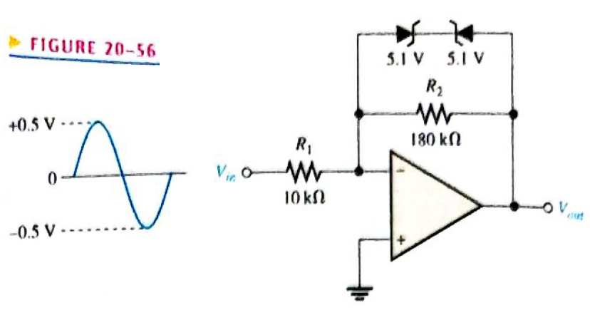
Chapter 20, Problem 27P
Show the output voltage for the zener diode limiter in Figure 20-56.
Expert Solution & Answer
Want to see the full answer?
Check out a sample textbook solution
Students have asked these similar questions
Pf correction,
A single stage amplifoer has a single stage of 60. The collector load of 500 ohms and the input impedance is 1kilo ohms. Calculate the overall gain when two such stages are cascaded through R-C coupling.
Which of the following is not an Active transducer ?
a.
RTD
b.
Photocell
c.
Piezoelectric Transducer
d.
Thermocouple
Chapter 20 Solutions
Electric Circuits Fundamentals & Lab Mnl Pk
Ch. 20 - An instrumentation amplifier requires separate...Ch. 20 - Instrumentation amplifiers have excellent...Ch. 20 - The higher the gain of an instrumentation...Ch. 20 - An isolation amplifier is the same as an...Ch. 20 - An isolation amplifier is commonly used in...Ch. 20 - Prob. 6TFQCh. 20 - Prob. 7TFQCh. 20 - Prob. 8TFQCh. 20 - An active limiter circuit uses a diode in the...Ch. 20 - Prob. 10TFQ
Ch. 20 - To make a basic instrumentation amplifier, it...Ch. 20 - Prob. 2STCh. 20 - Prob. 3STCh. 20 - Prob. 4STCh. 20 - Prob. 5STCh. 20 - Prob. 6STCh. 20 - Prob. 7STCh. 20 - Prob. 8STCh. 20 - In an OTA, the transconductance is controlled by...Ch. 20 - Prob. 10STCh. 20 - An OTA is basically a voltage-to-current amplifier...Ch. 20 - Prob. 12STCh. 20 - When the + input of the clamper op-amp is...Ch. 20 - Prob. 14STCh. 20 - Prob. 15STCh. 20 - Determine the voltage gains of op-amps A1 and A2...Ch. 20 - Prob. 2PCh. 20 - Prob. 3PCh. 20 - Prob. 4PCh. 20 - What is the voltage gain of the INA333...Ch. 20 - Determine the approximate bandwidth of the...Ch. 20 - Specify what you must do to change the gain of the...Ch. 20 - Determine the value of RG in Figure 20-46 for a...Ch. 20 - The op-amp in the input stage of a 3656Â KG...Ch. 20 - Determine the total voltage gain of each 3656KG in...Ch. 20 - Specify how you would change the total gain of the...Ch. 20 - Prob. 12PCh. 20 - Specify how you would connect each amplifier in...Ch. 20 - A certain OTA has an input voltage of 10 mV and an...Ch. 20 - A certain CYLA with a transconductance of 5000S...Ch. 20 - The output voltage of a certain OTA with a load...Ch. 20 - Prob. 17PCh. 20 - Prob. 18PCh. 20 - The OTA in Figure 20-49 functions an amplitude...Ch. 20 - Determine the trigger points for the Schmitt...Ch. 20 - Determine the output voltage waveform for the...Ch. 20 - Describe the output waveform of each circuit in...Ch. 20 - Determine the output voltage for the clamping...Ch. 20 - Repeat Problem 23 for the clamping circuit in...Ch. 20 - Describe the output waveform for each circuit in...Ch. 20 - Determine the output waveform for the active...Ch. 20 - Show the output voltage for the zener diode...Ch. 20 - Repeat Problem 27 if the input is reduced to a...Ch. 20 - What is the ideal output voltage for a peak...Ch. 20 - Determine the load current in each circuit of...Ch. 20 - Devise a circuit for remotely sensing temperature...Ch. 20 - Prob. 33PCh. 20 - Open file P20-34 and determine the fault.Ch. 20 - Prob. 35PCh. 20 - Open file P20-36 and determine the fault.
Knowledge Booster


Learn more about
Need a deep-dive on the concept behind this application? Look no further. Learn more about this topic, electrical-engineering and related others by exploring similar questions and additional content below.Similar questions
- Figure shows an improved series voltage regulator with current limit circuit protection 1. Calculate the approximate output current when the circuit triggers the short circuit protection. 2. Calculate the output voltage for the circuit.arrow_forwardLVDT transducer is .........type of transducer. digital passive active analogarrow_forward8.17c Copper extension leads are installed as shown in Figure 8.48b. For an output voltage of 7.947 mV and a reference junction temperature of 0⁰C, what is the temperature of the measuring junction?arrow_forward
- Draw the Supply voltage, output voltage and gate pulse on graph sheet for the firing angle α = 36°; α = 72°;arrow_forwardExplain the working of Capacitive type transducer with a neat diagram to measure the displacement.arrow_forward20- I. It has a simple structure II. Its efficiency is more than 90% III. It only requires one transistor. For which DC-DC converter the specifications given above are valid. a)Buck-Boost DC-DC Converter b) None C)Buck DC-DC Converter d) Boost DC-DC Converterarrow_forward
- Calculate sensitivity if the output voltage of a thermocouple goes from 40mV at 400C to 50mV at 900C. What are the units?arrow_forwardSketch and explain the output for the circuit of given parameters. The generator signal is a sine wave with a 10V peak. The diode is germanium and has a forward resistance rf of 25 ohms. (Using Third Diode Approximation)arrow_forwardDifine the diodd and explain it’s basing conditionsarrow_forward
- Ex. 1629. In Figure 1629 assume beta for all traces is 160. For the trace number 1, counted from the bottom, determine the base curent (uA) and collector current (mA). Base current is given in the legend. Calculate collector current using beta. ans:2arrow_forwardThe voltage of the Vin input signal will be 200mVp and the frequency will be 1KHz.Perform DC and AC analysis.arrow_forwardWrite short notes on: a) Diode switching Time b) DMOSFET c) Effect of Negative feedback on amplifier stability d) Clippers and clampersarrow_forward
arrow_back_ios
SEE MORE QUESTIONS
arrow_forward_ios
Recommended textbooks for you
 Introductory Circuit Analysis (13th Edition)Electrical EngineeringISBN:9780133923605Author:Robert L. BoylestadPublisher:PEARSON
 Delmar's Standard Textbook Of ElectricityElectrical EngineeringISBN:9781337900348Author:Stephen L. HermanPublisher:Cengage Learning
 Programmable Logic ControllersElectrical EngineeringISBN:9780073373843Author:Frank D. PetruzellaPublisher:McGraw-Hill Education
 Fundamentals of Electric CircuitsElectrical EngineeringISBN:9780078028229Author:Charles K Alexander, Matthew SadikuPublisher:McGraw-Hill Education
 Electric Circuits. (11th Edition)Electrical EngineeringISBN:9780134746968Author:James W. Nilsson, Susan RiedelPublisher:PEARSON
 Engineering ElectromagneticsElectrical EngineeringISBN:9780078028151Author:Hayt, William H. (william Hart), Jr, BUCK, John A.Publisher:Mcgraw-hill Education,
Introductory Circuit Analysis (13th Edition)
Electrical Engineering
ISBN:9780133923605
Author:Robert L. Boylestad
Publisher:PEARSON
Delmar's Standard Textbook Of Electricity
Electrical Engineering
ISBN:9781337900348
Author:Stephen L. Herman
Publisher:Cengage Learning
Programmable Logic Controllers
Electrical Engineering
ISBN:9780073373843
Author:Frank D. Petruzella
Publisher:McGraw-Hill Education
Fundamentals of Electric Circuits
Electrical Engineering
ISBN:9780078028229
Author:Charles K Alexander, Matthew Sadiku
Publisher:McGraw-Hill Education
Electric Circuits. (11th Edition)
Electrical Engineering
ISBN:9780134746968
Author:James W. Nilsson, Susan Riedel
Publisher:PEARSON
Engineering Electromagnetics
Electrical Engineering
ISBN:9780078028151
Author:Hayt, William H. (william Hart), Jr, BUCK, John A.
Publisher:Mcgraw-hill Education,
Electrical Engineering: Ch 5: Operational Amp (2 of 28) Inverting Amplifier-Basic Operation; Author: Michel van Biezen;https://www.youtube.com/watch?v=x2xxOKOTwM4;License: Standard YouTube License, CC-BY