
Electric Circuits Fundamentals & Lab Mnl Pk
8th Edition
ISBN: 9780136125136
Author: Unknown
Publisher: PEARSON
expand_more
expand_more
format_list_bulleted
Concept explainers
Videos
Textbook Question
Chapter 20, Problem 6P
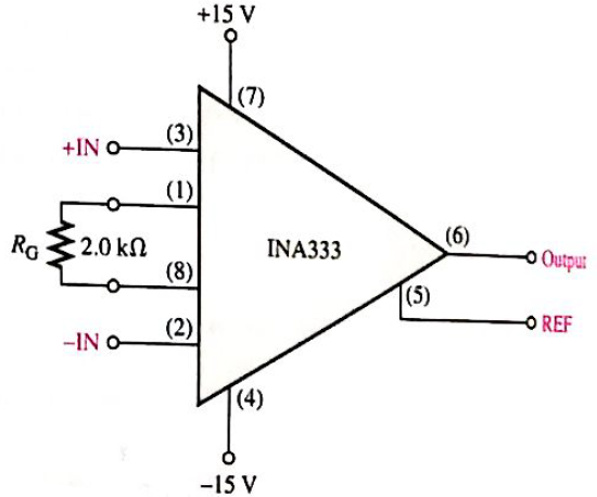
Determine the approximate bandwidth of the amplifier in Figure 20-46. Use the graph in Figure 20-6.
Expert Solution & Answer
Want to see the full answer?
Check out a sample textbook solution
Students have asked these similar questions
Determine the bandwidth of a two stage amplifier if you know the following information: The lower critical frequency for both stages is 125 Hz and the upper critical frequencies for the first and the second stages are 3MH2 and 2.5MHz respectively.
Draw a graph of the output voltage for the SC integrator as shown for five clock periods if C1 = 4C2, υI = 1 V, and υo(0) = 0.
true or false
The drop-off rate for low and high frequency regions is (-6 dB/octave) if the amplification stages are identical
Chapter 20 Solutions
Electric Circuits Fundamentals & Lab Mnl Pk
Ch. 20 - An instrumentation amplifier requires separate...Ch. 20 - Instrumentation amplifiers have excellent...Ch. 20 - The higher the gain of an instrumentation...Ch. 20 - An isolation amplifier is the same as an...Ch. 20 - An isolation amplifier is commonly used in...Ch. 20 - Prob. 6TFQCh. 20 - Prob. 7TFQCh. 20 - Prob. 8TFQCh. 20 - An active limiter circuit uses a diode in the...Ch. 20 - Prob. 10TFQ
Ch. 20 - To make a basic instrumentation amplifier, it...Ch. 20 - Prob. 2STCh. 20 - Prob. 3STCh. 20 - Prob. 4STCh. 20 - Prob. 5STCh. 20 - Prob. 6STCh. 20 - Prob. 7STCh. 20 - Prob. 8STCh. 20 - In an OTA, the transconductance is controlled by...Ch. 20 - Prob. 10STCh. 20 - An OTA is basically a voltage-to-current amplifier...Ch. 20 - Prob. 12STCh. 20 - When the + input of the clamper op-amp is...Ch. 20 - Prob. 14STCh. 20 - Prob. 15STCh. 20 - Determine the voltage gains of op-amps A1 and A2...Ch. 20 - Prob. 2PCh. 20 - Prob. 3PCh. 20 - Prob. 4PCh. 20 - What is the voltage gain of the INA333...Ch. 20 - Determine the approximate bandwidth of the...Ch. 20 - Specify what you must do to change the gain of the...Ch. 20 - Determine the value of RG in Figure 20-46 for a...Ch. 20 - The op-amp in the input stage of a 3656Â KG...Ch. 20 - Determine the total voltage gain of each 3656KG in...Ch. 20 - Specify how you would change the total gain of the...Ch. 20 - Prob. 12PCh. 20 - Specify how you would connect each amplifier in...Ch. 20 - A certain OTA has an input voltage of 10 mV and an...Ch. 20 - A certain CYLA with a transconductance of 5000S...Ch. 20 - The output voltage of a certain OTA with a load...Ch. 20 - Prob. 17PCh. 20 - Prob. 18PCh. 20 - The OTA in Figure 20-49 functions an amplitude...Ch. 20 - Determine the trigger points for the Schmitt...Ch. 20 - Determine the output voltage waveform for the...Ch. 20 - Describe the output waveform of each circuit in...Ch. 20 - Determine the output voltage for the clamping...Ch. 20 - Repeat Problem 23 for the clamping circuit in...Ch. 20 - Describe the output waveform for each circuit in...Ch. 20 - Determine the output waveform for the active...Ch. 20 - Show the output voltage for the zener diode...Ch. 20 - Repeat Problem 27 if the input is reduced to a...Ch. 20 - What is the ideal output voltage for a peak...Ch. 20 - Determine the load current in each circuit of...Ch. 20 - Devise a circuit for remotely sensing temperature...Ch. 20 - Prob. 33PCh. 20 - Open file P20-34 and determine the fault.Ch. 20 - Prob. 35PCh. 20 - Open file P20-36 and determine the fault.
Knowledge Booster


Learn more about
Need a deep-dive on the concept behind this application? Look no further. Learn more about this topic, electrical-engineering and related others by exploring similar questions and additional content below.Similar questions
- IL. K type thermocouple having a range of 0 — 350 °C and a sensitivity of 40 pV/°C. The signal is connected to an instrumentation amplifier before interfacing it with 5V analog to digital converter. Design a suitable instrumentation amplifier circuit. Vsupplyarrow_forwardAt the high cut-off frequency, the peak output voltage of a certain amplifier is10 V. The peak voltage at the pass-band of the amplifier is14.14 V6.37 V7.07 V10 V.arrow_forwardSelf generating type transducers are _____ transducers. a. Inverse b. Active c. Passive d. Secondaryarrow_forward
- Prove that class B power amplifier eliminates the even harmonics. Also explain the mainlimitation of the class B power amplifier.arrow_forwardq15 The phase shift between the input signal and the output signal of Buffer(voltage follower) is 0º 60º 90º 180ºarrow_forwardDetermine the voltage gain plz λ is not 0 ..arrow_forward
- For the circuit shown in attached figure, calculate the closed-loop voltage gain ______. 2.calculate the instantaneous voltage on the negative terminal when the signal voltage is +1V ________V 3.calculate the instantaneous voltage across RF when the signal voltage is + 1V _________V 4.arrow_forwardWhich of the following statement(s) is/are true? Negative feedback is applied in a zero crossing detector circuit. Time constant formula is same for both integrator and differentiator circuit. It is possible to design non-inverting adder circuit. Capacitive reactance decreases as frequency increases. In an oscillator, the oscillation frequency is determined by the tank circuitarrow_forwardAn A/D converter has the following circuit on its input port. a. bandpass filter b. high pass filter c. Sample and Hold circuit d. Low pass filter e. Amplifierarrow_forward
- Identify the transducer which converts input alternating current to output potential differenc . a/ LVDT b/ R to V converter c/ thermometrer d/ Rotameterarrow_forwardamplifer gain caklcultionsarrow_forwardHi, I need your help on the following question:Design an adapter circuit that has the input 120 rms 60 Hz and the output 12V 1Aarrow_forward
arrow_back_ios
SEE MORE QUESTIONS
arrow_forward_ios
Recommended textbooks for you
 Introductory Circuit Analysis (13th Edition)Electrical EngineeringISBN:9780133923605Author:Robert L. BoylestadPublisher:PEARSON
 Delmar's Standard Textbook Of ElectricityElectrical EngineeringISBN:9781337900348Author:Stephen L. HermanPublisher:Cengage Learning
 Programmable Logic ControllersElectrical EngineeringISBN:9780073373843Author:Frank D. PetruzellaPublisher:McGraw-Hill Education
 Fundamentals of Electric CircuitsElectrical EngineeringISBN:9780078028229Author:Charles K Alexander, Matthew SadikuPublisher:McGraw-Hill Education
 Electric Circuits. (11th Edition)Electrical EngineeringISBN:9780134746968Author:James W. Nilsson, Susan RiedelPublisher:PEARSON
 Engineering ElectromagneticsElectrical EngineeringISBN:9780078028151Author:Hayt, William H. (william Hart), Jr, BUCK, John A.Publisher:Mcgraw-hill Education,
Introductory Circuit Analysis (13th Edition)
Electrical Engineering
ISBN:9780133923605
Author:Robert L. Boylestad
Publisher:PEARSON
Delmar's Standard Textbook Of Electricity
Electrical Engineering
ISBN:9781337900348
Author:Stephen L. Herman
Publisher:Cengage Learning
Programmable Logic Controllers
Electrical Engineering
ISBN:9780073373843
Author:Frank D. Petruzella
Publisher:McGraw-Hill Education
Fundamentals of Electric Circuits
Electrical Engineering
ISBN:9780078028229
Author:Charles K Alexander, Matthew Sadiku
Publisher:McGraw-Hill Education
Electric Circuits. (11th Edition)
Electrical Engineering
ISBN:9780134746968
Author:James W. Nilsson, Susan Riedel
Publisher:PEARSON
Engineering Electromagnetics
Electrical Engineering
ISBN:9780078028151
Author:Hayt, William H. (william Hart), Jr, BUCK, John A.
Publisher:Mcgraw-hill Education,
Multistage Transistor Audio Amplifier Circuit; Author: The Organic Chemistry Tutor;https://www.youtube.com/watch?v=LJrL9N9uhkE;License: Standard Youtube License