
Electric Circuits Fundamentals & Lab Mnl Pk
8th Edition
ISBN: 9780136125136
Author: Unknown
Publisher: PEARSON
expand_more
expand_more
format_list_bulleted
Concept explainers
Videos
Textbook Question
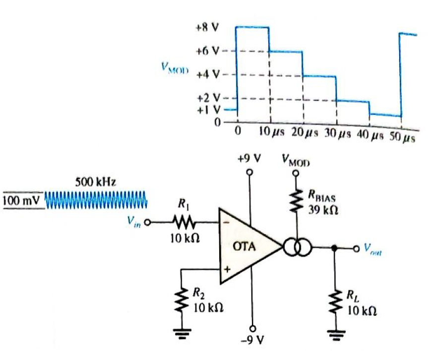
Chapter 20, Problem 19P
The OTA in Figure 20-49 functions an amplitude modulation circuit. Determine the output voltage waveform for the given input waveforms assuming
Expert Solution & Answer
Want to see the full answer?
Check out a sample textbook solution
Students have asked these similar questions
Wien bridge oscillator uses the following components, R1 = 150 k, R2 = 220 k, C1 =
220 pF and C2 = 150 pF. Determine the frequency of oscillations.
q15
The phase shift between the input signal and the output signal of Buffer(voltage follower) is
0º
60º
90º
180º
Please Solve this Question:
Design a Relaxation oscillator (using 1 OPAMP, 3 resistors and 1 capacitor) togenerate a square waveform of period 220us and 50% duty cycle.
Chapter 20 Solutions
Electric Circuits Fundamentals & Lab Mnl Pk
Ch. 20 - An instrumentation amplifier requires separate...Ch. 20 - Instrumentation amplifiers have excellent...Ch. 20 - The higher the gain of an instrumentation...Ch. 20 - An isolation amplifier is the same as an...Ch. 20 - An isolation amplifier is commonly used in...Ch. 20 - Prob. 6TFQCh. 20 - Prob. 7TFQCh. 20 - Prob. 8TFQCh. 20 - An active limiter circuit uses a diode in the...Ch. 20 - Prob. 10TFQ
Ch. 20 - To make a basic instrumentation amplifier, it...Ch. 20 - Prob. 2STCh. 20 - Prob. 3STCh. 20 - Prob. 4STCh. 20 - Prob. 5STCh. 20 - Prob. 6STCh. 20 - Prob. 7STCh. 20 - Prob. 8STCh. 20 - In an OTA, the transconductance is controlled by...Ch. 20 - Prob. 10STCh. 20 - An OTA is basically a voltage-to-current amplifier...Ch. 20 - Prob. 12STCh. 20 - When the + input of the clamper op-amp is...Ch. 20 - Prob. 14STCh. 20 - Prob. 15STCh. 20 - Determine the voltage gains of op-amps A1 and A2...Ch. 20 - Prob. 2PCh. 20 - Prob. 3PCh. 20 - Prob. 4PCh. 20 - What is the voltage gain of the INA333...Ch. 20 - Determine the approximate bandwidth of the...Ch. 20 - Specify what you must do to change the gain of the...Ch. 20 - Determine the value of RG in Figure 20-46 for a...Ch. 20 - The op-amp in the input stage of a 3656Â KG...Ch. 20 - Determine the total voltage gain of each 3656KG in...Ch. 20 - Specify how you would change the total gain of the...Ch. 20 - Prob. 12PCh. 20 - Specify how you would connect each amplifier in...Ch. 20 - A certain OTA has an input voltage of 10 mV and an...Ch. 20 - A certain CYLA with a transconductance of 5000S...Ch. 20 - The output voltage of a certain OTA with a load...Ch. 20 - Prob. 17PCh. 20 - Prob. 18PCh. 20 - The OTA in Figure 20-49 functions an amplitude...Ch. 20 - Determine the trigger points for the Schmitt...Ch. 20 - Determine the output voltage waveform for the...Ch. 20 - Describe the output waveform of each circuit in...Ch. 20 - Determine the output voltage for the clamping...Ch. 20 - Repeat Problem 23 for the clamping circuit in...Ch. 20 - Describe the output waveform for each circuit in...Ch. 20 - Determine the output waveform for the active...Ch. 20 - Show the output voltage for the zener diode...Ch. 20 - Repeat Problem 27 if the input is reduced to a...Ch. 20 - What is the ideal output voltage for a peak...Ch. 20 - Determine the load current in each circuit of...Ch. 20 - Devise a circuit for remotely sensing temperature...Ch. 20 - Prob. 33PCh. 20 - Open file P20-34 and determine the fault.Ch. 20 - Prob. 35PCh. 20 - Open file P20-36 and determine the fault.
Knowledge Booster


Learn more about
Need a deep-dive on the concept behind this application? Look no further. Learn more about this topic, electrical-engineering and related others by exploring similar questions and additional content below.Similar questions
- Draw block diagram /circuit diagram of the ff. FM circuits and discuss the operation. 2. FM Demodulator a. SLOPE DETECTORarrow_forwardSemicinductrsarrow_forwardHi, I need your help on the following question:Design an adapter circuit that has the input 120 rms 60 Hz and the output 12V 1Aarrow_forward
- 2. A PM signal has a deviation ratio of 3. The maximum modulating signal is 5 kHz. The bandwidth of the signal is correct answer: 20kHzarrow_forwardA receiver has two tuned-circuit stages before the mixer, each with a Q of 75. The signal frequency is 100.1 MHz, and the IF is 10.7 MHz. The local oscillator uses HIS. What is the total IFRR in dB.arrow_forwardSanlg abis A 2nd order system has response curve with overshoot percent of 50% and period of oscillations 0.2 * ?sec. what is Mr and Wr 6.6 O 10,10 O 16,16 O No of the above answer Oarrow_forward
- IL. K type thermocouple having a range of 0 — 350 °C and a sensitivity of 40 pV/°C. The signal is connected to an instrumentation amplifier before interfacing it with 5V analog to digital converter. Design a suitable instrumentation amplifier circuit. Vsupplyarrow_forward2- Describe the effect of clock frequency on the output af the integrator. 4- Give the advantage and disadvantage of Delta Modulation 5- Compare between Delta Modulation and Pulse Code Modulationarrow_forwardIn a Common Emitter (CE) Fixed Bias (FB) configuration, the output impedance is almost equal to _____? a.ro b.Rb c.re d.Rcarrow_forward
- Identify the transducer which converts input alternating current to output potential differenc . a/ LVDT b/ R to V converter c/ thermometrer d/ Rotameterarrow_forwardamplifer gain caklcultionsarrow_forwardThe oscillation frequency ofthe oscillation circuit is usually determined by ( ) A.Magnification B.Feedback coefficient C.Stabilize circuit parameters D. Frequency selection network parametersarrow_forward
arrow_back_ios
SEE MORE QUESTIONS
arrow_forward_ios
Recommended textbooks for you
 Introductory Circuit Analysis (13th Edition)Electrical EngineeringISBN:9780133923605Author:Robert L. BoylestadPublisher:PEARSON
 Delmar's Standard Textbook Of ElectricityElectrical EngineeringISBN:9781337900348Author:Stephen L. HermanPublisher:Cengage Learning
 Programmable Logic ControllersElectrical EngineeringISBN:9780073373843Author:Frank D. PetruzellaPublisher:McGraw-Hill Education
 Fundamentals of Electric CircuitsElectrical EngineeringISBN:9780078028229Author:Charles K Alexander, Matthew SadikuPublisher:McGraw-Hill Education
 Electric Circuits. (11th Edition)Electrical EngineeringISBN:9780134746968Author:James W. Nilsson, Susan RiedelPublisher:PEARSON
 Engineering ElectromagneticsElectrical EngineeringISBN:9780078028151Author:Hayt, William H. (william Hart), Jr, BUCK, John A.Publisher:Mcgraw-hill Education,
Introductory Circuit Analysis (13th Edition)
Electrical Engineering
ISBN:9780133923605
Author:Robert L. Boylestad
Publisher:PEARSON
Delmar's Standard Textbook Of Electricity
Electrical Engineering
ISBN:9781337900348
Author:Stephen L. Herman
Publisher:Cengage Learning
Programmable Logic Controllers
Electrical Engineering
ISBN:9780073373843
Author:Frank D. Petruzella
Publisher:McGraw-Hill Education
Fundamentals of Electric Circuits
Electrical Engineering
ISBN:9780078028229
Author:Charles K Alexander, Matthew Sadiku
Publisher:McGraw-Hill Education
Electric Circuits. (11th Edition)
Electrical Engineering
ISBN:9780134746968
Author:James W. Nilsson, Susan Riedel
Publisher:PEARSON
Engineering Electromagnetics
Electrical Engineering
ISBN:9780078028151
Author:Hayt, William H. (william Hart), Jr, BUCK, John A.
Publisher:Mcgraw-hill Education,
What is a Power Amplifier, And Do I Need One?; Author: Sweetwater;https://www.youtube.com/watch?v=2wkmSm4V00M;License: Standard Youtube License