
Tutorials in Introductory Physics
1st Edition
ISBN: 9780130970695
Author: Peter S. Shaffer, Lillian C. McDermott
Publisher: Addison Wesley
expand_more
expand_more
format_list_bulleted
Videos
Textbook Question
Chapter 20.1, Problem 3bTH
A wire is now added to the circuit as shown.
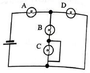
i. Does the brightness of bulb C increase, decrease, or remain the same? Explain your reasoning.
ii. Does the brightness of bulb Aincrease, decrease, or remain the same? Explain.
iii. Does the current through the battery increase, decrease or remain the same? Explain.
Expert Solution & Answer
Want to see the full answer?
Check out a sample textbook solution
Students have asked these similar questions
1. a) For the circuit below, what is the terminal voltage of the battery? b) If resistor R is added in parallel to the circuit as shown, what is the effect on the terminal voltage? (increasing, no change, decreasing) c) Using principles of physics, explain the choice for b).
In circuit 6, how is bulb C connected to A and B? Parallel
What are the total resistance Rtot and the current flowing from the battery I in circuit 6?Rtot = _____ ΩI = _____ A
If the EMF is 12 V, then determine the following. (a) What is the equivalent resistance of the circuit in the diagram? (b) What is the voltage across the 4.0 Ω resistor? (c) What is the current in the 3.0 Ω resistor? (d) Show your steps in the process of reducing the circuit.
Chapter 20 Solutions
Tutorials in Introductory Physics
Ch. 20.1 - In tutorial, you compared the relative brightness...Ch. 20.1 - Use the model for electric current to rank the...Ch. 20.1 - Rang the brightness of the bulbs. Explain your...Ch. 20.1 - A wire is now added to the circuit as shown. i....Ch. 20.1 - Rank the networks according to their equivalent...Ch. 20.1 - How does adding a single bulb to a circuit in...Ch. 20.1 - How does adding a single bulb to a circuit in...Ch. 20.1 - The network AE above are connected, in turn, to...Ch. 20.1 - Rank the bulbs in order from brightest to dimmest....Ch. 20.1 - Suppose that a switch has been added to the...
Ch. 20.2 - The circuit at right consists of a bulb in series...Ch. 20.2 - The circuit at right consists of a bulb in series...Ch. 20.2 - The circuit at right consists of a bulb in series...Ch. 20.2 - In the circuit at right, the voltage across bulb 1...Ch. 20.2 - Prob. 2bTHCh. 20.2 - Box A and box B are now interchanged. It is...Ch. 20.2 - Consider the circuit as shown. i. Rank bulbs A, B,...Ch. 20.2 - b. A student cuts the write between bulbs A and C...Ch. 20.2 - Consider the following discussion between two...Ch. 20.2 - Rank bulbs 16 in order or brightness. Explain your...Ch. 20.2 - Rank the voltages across the bulbs. Explain your...Ch. 20.2 - Write an equation that relates the voltage across...Ch. 20.2 - Bulb 1 is removed from its socket. i. Does the...Ch. 20.3 - Describe the behavior of the bulb in the two...Ch. 20.3 - A second identical bulb is flow added to the...Ch. 20.3 - Just after the switch is closed: • what is the...Ch. 20.3 - A long time after the switch is closed: • rank the...Ch. 20.3 - Summarize your results by describing the behavior...
Additional Science Textbook Solutions
Find more solutions based on key concepts
Write the SI unit for each abbreviation.
29. 27 mm
Applied Physics (11th Edition)
56. A container holds 1.0 g of oxygen at a pressure of 8.0 atm.
a. How much heat is required to increase the te...
College Physics: A Strategic Approach (4th Edition)
The correct option.
College Physics: A Strategic Approach (3rd Edition)
Consider the following debate between two students regarding the energy given off by the Sun.
Student 1: I thin...
Lecture- Tutorials for Introductory Astronomy
Choose the best answer to each of the following. Explain your reasoning. In Ptolemys geometric model, the retro...
The Cosmic Perspective Fundamentals (2nd Edition)
Knowledge Booster


Learn more about
Need a deep-dive on the concept behind this application? Look no further. Learn more about this topic, physics and related others by exploring similar questions and additional content below.Similar questions
- 4. i. How can four 100 kΩ resistors be connected so that the equivalent resistance of the four equals 250 kΩ? Sketch the arrangement, describe the resistor arrangement in words, and justify your picture by calculating the equivalent resistance. ii. Repeat part i. above with four 100 F capacitors and an equivalent capacitance of 75 F.arrow_forwardPART A In (Figure 1), what fraction of current II goes through the 3 ΩΩ resistor? Part B : Second picturearrow_forwardConsider the circuit diagram depicted in the figure. Part (a) If the current through the top branch is I2 = 0.025 A, what is the current through the bottom, I3, in amps?arrow_forward
- Help please, Show your complete (step-by-step) analysis and solution, with the appropriate equations and/or diagrams. Thank youu! 1. Originally, a circuit contains four (4) identical resistors in parallel across a battery. If one resistor is removed, what happens to the value of total current, total resistance and total voltage? Express the new quantities in terms of the original quantities.arrow_forwardA circuit contains three identical bulbs lit by connection to a single battery. When a wire is connected across the terminals of one of the bulbs, it goes out and so does another one of the bulbs. The remaining bulb becomes brighter. a.) Sketch the circuit in which the two bulbs must have been arranged. Explain reasoning b.) What would happen to the brightness of the other two bulbs if the wire were connected across the terminals of the bulb that does not go out in part (a)?arrow_forward1) What are the units of the slope of the line? 2) How would you use the slope to calculate the resistance of each resistor? Hint: use the units to guide your thinking here. 3) Please use your graphs to calculate the resistance of each resistor. Then, please find the percent error between your calculated values and the measured value (9.7 ㏀) of each resistor.arrow_forward
- Identical bulbs are shown in the circuit. 1) Is bulb A brighter, dimmer, or the same brightness as bulb B? Explain 2) Is the current through bulb D greater that or less that, or equal to the current through bulb F. Explain. 3) If bulb F is unscrewed from its socket, does bulb B become brighter, dimmer, or stay the same. Explain.arrow_forwardConsider the circuit shown in (Figure 1). A)What are the magnitude and direction of the current in the 20 Ω resistor in (Figure 1)? Express your answer with the appropriate units. Enter positive value if the current is clockwise and negative value if the current is counterclockwise.arrow_forwardSix circuits containing a battery and two or more bulbs are shown here. D. What are the total resistance Rtot and the current flowing from the battery I in circuit 2?Rtot = ΩI = AE. In circuit 3, how is bulb C connected to A and B? ---Select--- series parallel neither What are the total resistance Rtot and the current flowing from the battery I in circuit 3?Rtot = ΩI = AF. In circuit 6, how is bulb C connected to A and B? ---Select--- series parallel neither What are the total resistance Rtot and the current flowing from the battery I in circuit 6?Rtot = ΩI = Aarrow_forward
- A series circuit consists of three identical lamps connected to a battery as shown in the figure below. The switch S, originally open, is closed. (i) What then happens to the brightness of lamp B? (ii) What happens to the brightness of lamp C? (iii) What happens to the current in the battery? (iv) What happens to the potential difference across lamp A? (v) What happens to the potential difference across lamp C? (vi) What happens to the total power delivered to the lamps by the battery?arrow_forwardTake three resistors.R1=25 ohms, R2=17 ohms and R3 = 3 ohms. Let V0 = 30 V. Now, connect the resistors as shown in the figure, and connect them to the power supply. Record the voltage across each resistor, using the voltmeter. a. Are the voltages V1, V2 and V3 equal to each other? Why or why not? b. Calculate the total voltage V = V1 + V2 + V3. Explain why it has the value it does. c. Use Ohm’s law to calculate the current through each resistor. d. Calculate the effective resistance of the circuit. e. Construct another circuit by replacing the 3 resistors with the single effective resistance. please solve all points..arrow_forwardI need help with d,e,f Refer to the values in the box for the circuit shown in Figure. You can assume an ideal battery d.For each resistor, calculate the current through the resistor with Sclosed. e.For each resistor, does the current increase or decrease when S isclosed? Why? f.Calculate the power dissipated in each resistor with S closed andopen and show that the total matches the power generated by the emf. i posted a pic of work for a to c a.What is the potential difference, Vab, between points a and b when the switch S is open andb.What is the potential difference, Vab, betweenpoints a and b when S is closed?c.For each resistor, calculate the current through the resistor with Sopenarrow_forward
arrow_back_ios
SEE MORE QUESTIONS
arrow_forward_ios
Recommended textbooks for you
 Glencoe Physics: Principles and Problems, Student...PhysicsISBN:9780078807213Author:Paul W. ZitzewitzPublisher:Glencoe/McGraw-Hill
Glencoe Physics: Principles and Problems, Student...
Physics
ISBN:9780078807213
Author:Paul W. Zitzewitz
Publisher:Glencoe/McGraw-Hill
Series & Parallel - Potential Divider Circuits - GCSE & A-level Physics; Author: Science Shorts;https://www.youtube.com/watch?v=vf8HVTVvsdw;License: Standard YouTube License, CC-BY