
MECHANICS OF MATERIALS
7th Edition
ISBN: 9781260471076
Author: BEER
Publisher: MCG
expand_more
expand_more
format_list_bulleted
Concept explainers
Videos
Textbook Question
Chapter 2.1, Problem 18P
The brass tube AB (E = 105 GPa) has a cross-sectional area of 140 mm2 and is fitted with a plug at A. The tube is attached at B to a rigid plate that is itself attached at C to the bottom of an aluminum cylinder (E = 72 GPa) with a cross-sectional area of 250 mm2. The cylinder is then hung from a support at D. In order to close the cylinder, the plug must move down through 1 mm. Determine the force P that must be applied to the cylinder.
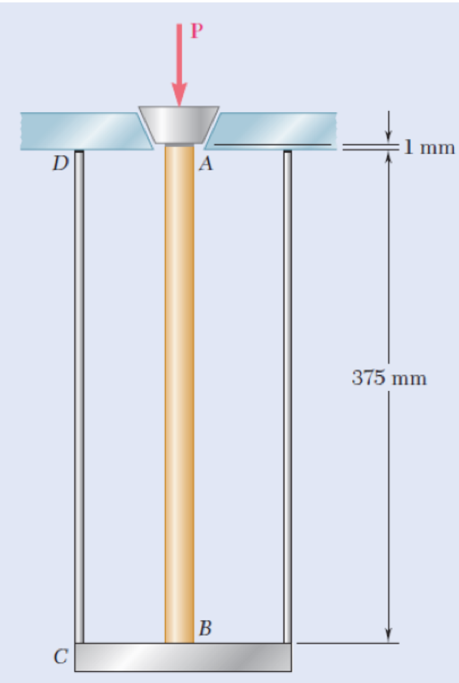
Fig. P2.18
Expert Solution & Answer
Want to see the full answer?
Check out a sample textbook solution
Students have asked these similar questions
The brass tube AB (E = 105 GPa) has a cross-sectional areaof 138 mm² and is fitted with a plug at A. The tube is attached atB to a rigid plate that is itself attached at C to the bottom of analuminum cylinder (E = 70 GPa) with a cross-sectional areaof 250 mm². The cylinder is then hung from a support at D. In orderto close the cylinder, the plug must move down through 1.2 mm. Determine the force P that must be applied to the cylinder.
The load of 2000 lb is to be supported by the two vertical steel wires for which sY = 70 ksi. Originally wire AB is 60 in. long and wire AC is 60.04 in. long. Determine the cross-sectional area of AB if the load is to be shared equally between both wires. Wire AC has a cross-sectional area of 0.02 in2. Est = 29.0(103) ksi.
A solid aluminum [E = 64 GPa] rod (1) is connected to a solid bronze [E = 114 GPa] rod (2) at flange B, as shown. Aluminum rod (1) has an outside diameter of 36 mm and bronze rod (2) has an outside diameter of 17 mm. The normal stress in the aluminum rod must be limited to 124 MPa, and the normal stress in the bronze rod must be limited to 92 MPa. Assume L1 = 168 mm and L2 = 399 mm. Determine: (a) the maximum downward load P that may be applied at flange B. (Answer: P = 146kN)(b) the deflection vB (downward is positive) of flange B at the load determined in part(a). (Answer: vB = .322 mm)
Chapter 2 Solutions
MECHANICS OF MATERIALS
Ch. 2.1 - A nylon thread is subjected to a 8.5-N tension...Ch. 2.1 - A 4.8-ft-long steel wire of 14 -in.-diameter is...Ch. 2.1 - An 18-m-long steel wire of 5-mm diameter is to be...Ch. 2.1 - Two gage marks are placed exactly 250 mm apart on...Ch. 2.1 - An aluminum pipe must not stretch more than 0.05...Ch. 2.1 - A control rod made of yellow brass must not...Ch. 2.1 - A steel control rod is 5.5 ft long and must not...Ch. 2.1 - A cast-iron tube is used to support a compressive...Ch. 2.1 - A 4-m-long steel rod must not stretch more than 3...Ch. 2.1 - A nylon thread is to be subjected to a 10-N...
Ch. 2.1 - A block of 10-in. length and 1.8 1.6-in. cross...Ch. 2.1 - A square yellow-brass bar must not stretch more...Ch. 2.1 - Rod BD is made of steel (E = 29 106 psi) and is...Ch. 2.1 - The 4-mm-diameter cable BC is made of a steel with...Ch. 2.1 - A single axial load of magnitude P = 15 kips is...Ch. 2.1 - A 250-mm-long aluminum tube (E = 70 GPa) of 36-mm...Ch. 2.1 - The specimen shown has been cut from a...Ch. 2.1 - The brass tube AB (E = 105 GPa) has a...Ch. 2.1 - Both portions of the rod ABC are made of an...Ch. 2.1 - The rod ABC is made of an aluminum for which E =...Ch. 2.1 - For the steel truss (E = 200 GPa) and loading...Ch. 2.1 - For the steel truss (E = 29 106 psi) and loading...Ch. 2.1 - Members AB and BC are made of steel (E = 29 106...Ch. 2.1 - The steel frame (E = 200 GPa) shown has a diagonal...Ch. 2.1 - Link BD is made of brass (E = 105 GPa) and has a...Ch. 2.1 - Members ABC and DEF are joined with steel links (E...Ch. 2.1 - Each of the links AB and CD is made of aluminum (E...Ch. 2.1 - The length of the 332-in.-diameter steel wire CD...Ch. 2.1 - A homogenous cable of length L and uniform cross...Ch. 2.1 - The vertical load P is applied at the center A of...Ch. 2.1 - Denoting by the "engineering strain'' in a...Ch. 2.1 - The volume of a tensile specimen is essentially...Ch. 2.3 - An axial centric force of magnitude P = 450 kN is...Ch. 2.3 - An axial centric force of magnitude P = 450 kN is...Ch. 2.3 - The 4.5-ft concrete post is reinforced with six...Ch. 2.3 - The 4.5-ft concrete post is reinforced with six...Ch. 2.3 - An axial force of 200 kW is applied to the...Ch. 2.3 - The length of the assembly shown decreases by 0.40...Ch. 2.3 - A polystyrene rod consisting of two cylindrical...Ch. 2.3 - Three steel rods (E = 29 106 psi) support an...Ch. 2.3 - Fig. P2.41 2.41 Two cylindrical rods, one of steel...Ch. 2.3 - Solve Prob. 2.41, assuming that rod AC is made of...Ch. 2.3 - Each of the rods BD and CE is made of brass (E =...Ch. 2.3 - The rigid bar AD is supported by two steel wires...Ch. 2.3 - The rigid bar ABC is suspended from three wines of...Ch. 2.3 - The rigid bar AD is supported by two steel wires...Ch. 2.3 - The aluminum shell is fully bonded to the brass...Ch. 2.3 - The aluminum shell is fully bonded to the brass...Ch. 2.3 - The brass shell (b = 11.6 10-6/F) is fully bonded...Ch. 2.3 - The concrete post (Ec = 3.6 106) psi and c = 5.5 ...Ch. 2.3 - A rod consisting of two cylindrical portions AB...Ch. 2.3 - A rod consisting of two cylindrical portions AB...Ch. 2.3 - Fig. P2.52 2.52 A rod consisting of two...Ch. 2.3 - The steel rails of a railroad (rack (Es = 200GPa,...Ch. 2.3 - Two steel bars (Es = 200 GPa and s = 11.7 10-6/C)...Ch. 2.3 - Determine the maximum load P that can be applied...Ch. 2.3 - An aluminum rod (Ea = 70 GPa, a = 23.6 10-6/C)...Ch. 2.3 - Knowing that a 0.02-in. gap exists when the...Ch. 2.3 - Determine (a) the compressive force in the bars...Ch. 2.3 - At room temperature (20C) a 0.5-mm gap exists...Ch. 2.9 - A standard tension test is used to determine the...Ch. 2.9 - A 2-m length of an aluminum pipe of 240-nun outer...Ch. 2.9 - A line of slope 4:10 has been scribed on a...Ch. 2.9 - A 2.75-kN tensile load is applied to a test coupon...Ch. 2.9 - Fig. P2.65 2.65 In a standard tensile test a steel...Ch. 2.9 - The change in diameter of a large steel bolt is...Ch. 2.9 - The brass rod AD is fitted with a jacket that is...Ch. 2.9 - A fabric used in air-inflated structures is...Ch. 2.9 - A 1-in. square was scribed on the side of a large...Ch. 2.9 - The block shown is made of a magnesium alloy for...Ch. 2.9 - The homogeneous plate ABCD is subjected to a...Ch. 2.9 - For a member under axial loading, express the...Ch. 2.9 - In many situations it is known that the normal...Ch. 2.9 - In many situations physical constraints prevent...Ch. 2.9 - The plastic block shown is bonded to a rigid...Ch. 2.9 - The plastic block shown is bonded to a rigid...Ch. 2.9 - Two blocks of rubber with a modulus of rigidity G...Ch. 2.9 - Fig. P2.77 and P2.78 2.78 Two blocks of rubber...Ch. 2.9 - An elastomeric bearing (G = 130 psi) is used to...Ch. 2.9 - 2.80 For the elastomeric bearing In Prob. 2.79...Ch. 2.9 - A vibration isolation unit consists of two blocks...Ch. 2.9 - Prob. 82PCh. 2.9 - Prob. 83PCh. 2.9 - Prob. 84PCh. 2.9 - Prob. 85PCh. 2.9 - A 2.75-kN tensile load is applied to a test coupon...Ch. 2.9 - A vibration isolation support consists of a rod A...Ch. 2.9 - Prob. 88PCh. 2.9 - Prob. 89PCh. 2.9 - Show that for any given material, the ratio G/E of...Ch. 2.9 - Prob. 91PCh. 2.9 - Prob. 92PCh. 2.13 - Knowing that, for the plate shown, the allowable...Ch. 2.13 - Knowing that P = 38 kN, determine the maximum...Ch. 2.13 - A hole is to be drilled in the plate at A. The...Ch. 2.13 - Fig. P2.95 and P2.96 2.96 (a) For P = 13 kips and...Ch. 2.13 - 2.97 Knowing that the hole has a diameter of 9 mm,...Ch. 2.13 - For P = 100 kN, determine the minimum plate...Ch. 2.13 - Prob. 99PCh. 2.13 - A centric axial force is applied to the steel bar...Ch. 2.13 - The cylindrical rod AB has a length L = 5 ft and a...Ch. 2.13 - Fig. P2.101 and P.102 2.102 The cylindrical rod AB...Ch. 2.13 - Rod AB is made of a mild steel that is assumed to...Ch. 2.13 - Prob. 104PCh. 2.13 - Rod ABC consists of two cylindrical portions and...Ch. 2.13 - Prob. 106PCh. 2.13 - Prob. 107PCh. 2.13 - Prob. 108PCh. 2.13 - Each cable has a cross-sectional area of 100 mm2...Ch. 2.13 - Prob. 110PCh. 2.13 - Two tempered-steel bars, each 316 in. thick, are...Ch. 2.13 - Prob. 112PCh. 2.13 - Prob. 113PCh. 2.13 - Prob. 114PCh. 2.13 - Prob. 115PCh. 2.13 - Prob. 116PCh. 2.13 - Prob. 117PCh. 2.13 - Prob. 118PCh. 2.13 - Prob. 119PCh. 2.13 - For the composite bar in Prob. 2.111, determine...Ch. 2.13 - Prob. 121PCh. 2.13 - Bar AB has a cross-sectional area of 1200 mm2 and...Ch. 2.13 - Bar AB has a cross-sectional area of 1200 mm2 and...Ch. 2 - The uniform wire ABC, of unstretched length 2l, is...Ch. 2 - The aluminum rod ABC (E = 10.1 106 psi), which...Ch. 2 - Two solid cylindrical rods are joined at B and...Ch. 2 - Prob. 127RPCh. 2 - Prob. 128RPCh. 2 - Prob. 129RPCh. 2 - A 4-ft concrete post is reinforced with four steel...Ch. 2 - The steel rods BE and CD each have a 16-mm...Ch. 2 - Prob. 132RPCh. 2 - Prob. 133RPCh. 2 - The aluminum test specimen shown is subjected to...Ch. 2 - Prob. 135RP
Knowledge Booster


Learn more about
Need a deep-dive on the concept behind this application? Look no further. Learn more about this topic, mechanical-engineering and related others by exploring similar questions and additional content below.Similar questions
- The rod BD is made of material with G1= 124 GPa has a diameter 34 mm is bonded to the tube CA at point B, the tube made of material with G2=211 GPa has an outer diameter 73 mm and wall thickness of 10 mm. If T1=579 N.m and T2=1042 N.m, answer the following questions: The maximum shear stress of the rod BD is The maximum shear stress of the tube CA is The maximum shear stress of the assembly is The angle of twist between D and B is The angle of twist between C and A is The angle of twist at D is Your answer The angle of twist between C and B is Your answer The reaction at point A isarrow_forwardA solid square steel bar is fixed at one end as shown, and is loaded with a 25 kg weight. If the limiting stress of the bar is 27.24 kPa determine the cross sectional area of the steel square bar and its dimensions.arrow_forwardThe 1021-kg uniform bar AB is suspended from two cables AC and BD each with cross-sectional area 472 mm2. Find the magnitude of P (in N) that can be safely applied to the bar if the stresses in AC and BD are limited to 110 MPa and 51 MPa, respectively. Express your answer in two decimal places.arrow_forward
- Two members AB and AC are made of material with E= 138 Gpa and each member has cross sectional area of A= 346 mm2. The members are used to support bar BC. If P=1917 N, L1= 242 mm , L2= 373 mm and L3= 459 mm . Answer the following questions. The tension in member AB? The tension in member CD? The elongation in member AB? The elongation in member CD? Vertical displacement of point E?arrow_forwardDetermine the largest weight W in N that can be supported by two wires shown in the figure.The stress in either wire is not to exceed 261 Mpa. The cross-sectional areas of wires AB and ACare 258 mm^2 and 320mm^2 respectively.arrow_forwardRigid bar ABC is supported by bronze rod (1) and aluminum rod (2), as shown. A concentrated load P is applied to the free end of aluminum rod (3). Bronze rod (1) has an elastic modulus of E1 = 15,000 ksi and a diameter of d1 = 0.50 in. Aluminum rod (2) has an elastic modulus of E2 = 10,000 ksi and a diameter of d2 = 0.85in. Aluminum rod (3) has a diameter of d3 = 1.00in. The yield strength of the bronze is 48 ksi and the yield strength of the aluminum is 40 ksi. Assume a = 2.5 ft, b = 1.5 ft, L1 = 6 ft, L2 = 8 ft, and L3 = 3 ft. (A) Calculate the cross-sectional areas of the three rods. in in.2 (B) For a factor of safety of 2.1, calculate the allowable stresses in the bronze and the aluminum rods. IN KSI. (C) What is the magnitude of load P that can safely be applied to the structure for a minimum factor of safety of 2.1? in kips (D) The pin used at B has an ultimate shear strength of 58 ksi. If a factor of safety of 2.5 is required, determine the allowable shear stress in this pin.…arrow_forward
- Rigid bar ABC is supported by bronze rod (1) and aluminum rod (2), as shown. A concentrated load P is applied to the free end of aluminum rod (3). Bronze rod (1) has an elastic modulus of E1 = 15,000 ksi and a diameter of d1 = 0.40 in. Aluminum rod (2) has an elastic modulus of E2 = 10,000 ksi and a diameter of d2 = 0.70in. Aluminum rod (3) has a diameter of d3 = 1.00in. The yield strength of the bronze is 48 ksi and the yield strength of the aluminum is 40 ksi. Assume a = 2.5 ft, b = 1.5 ft, L1 = 6 ft, L2 = 8 ft, and L3 = 3 ft.arrow_forwardThe rectangular bar is connected to the support bracket with a 11-mm-diameter pin. The bar width is w = 60 mm and the bar thickness is 10 mm. Each side of the bracket has the same dimensions as the bar. The average shear stress in the pin cannot exceed 120 MPa, the bearing stress in the bar cannot exceed 120 MPa, and the bearing stress in the bracket cannot exceed 120 MPa. Determine the maximum value of Pmax that can be supported by the structure.arrow_forwardAn aluminum strut 2.50m long has a rectangular section 60mm by 30mm. A bolt through each end secures the strut so that it acts as a hinged column about an axis perpendicular to the 60 mm dimension and as a fixed ended column about an axis perpendicular to the 30mm dimension. Determine the safe central load using a factor of safety of 2.5 and E = 70 Gpa.arrow_forward
- The five-bolt connection shown must support an applied load of P = 330 kN. If the average shear stress in the bolts must be limited to 295 MPa, determine the minimum bolt diameter that may be used in the connection.arrow_forwardA device consists of a horizontal beam ABCsupported by two vertical bars BD and CE. Bar CEis pinned at both ends but bar BD is fixed to thefoundation at its lower end. The distance from A toB is 600 mm and from B to C is 350 mm. Bars BDand CE have lengths of 350 mm and 450 mm, respectively,and their cross-sectional area is 720 mm2. Thebars are made of steel having a modulus of elasticityE = 200 GPa. If load P is 20 kN, calculate the displacementat point A.arrow_forwardTHe bracket shown is made of cold drawn steel with Sy=400MPa and Su=480 MPa, and is fastened to a beam made of the same material by five rivets that are made of a steel with Sy=300 MPa and Sut=365 MPa. The thickness of the bracket and the beam are 12 mm and 16 mm respectively.Diameters of the rivets are 20 mm. What safe load F(steady) can be supported by the riveted joint for a factor of safety of 2. Use distortion energy theory of failure.arrow_forward
arrow_back_ios
SEE MORE QUESTIONS
arrow_forward_ios
Recommended textbooks for you
 Elements Of ElectromagneticsMechanical EngineeringISBN:9780190698614Author:Sadiku, Matthew N. O.Publisher:Oxford University Press
 Mechanics of Materials (10th Edition)Mechanical EngineeringISBN:9780134319650Author:Russell C. HibbelerPublisher:PEARSON
 Thermodynamics: An Engineering ApproachMechanical EngineeringISBN:9781259822674Author:Yunus A. Cengel Dr., Michael A. BolesPublisher:McGraw-Hill Education
 Control Systems EngineeringMechanical EngineeringISBN:9781118170519Author:Norman S. NisePublisher:WILEY
 Mechanics of Materials (MindTap Course List)Mechanical EngineeringISBN:9781337093347Author:Barry J. Goodno, James M. GerePublisher:Cengage Learning
 Engineering Mechanics: StaticsMechanical EngineeringISBN:9781118807330Author:James L. Meriam, L. G. Kraige, J. N. BoltonPublisher:WILEY
Elements Of Electromagnetics
Mechanical Engineering
ISBN:9780190698614
Author:Sadiku, Matthew N. O.
Publisher:Oxford University Press
Mechanics of Materials (10th Edition)
Mechanical Engineering
ISBN:9780134319650
Author:Russell C. Hibbeler
Publisher:PEARSON
Thermodynamics: An Engineering Approach
Mechanical Engineering
ISBN:9781259822674
Author:Yunus A. Cengel Dr., Michael A. Boles
Publisher:McGraw-Hill Education
Control Systems Engineering
Mechanical Engineering
ISBN:9781118170519
Author:Norman S. Nise
Publisher:WILEY
Mechanics of Materials (MindTap Course List)
Mechanical Engineering
ISBN:9781337093347
Author:Barry J. Goodno, James M. Gere
Publisher:Cengage Learning
Engineering Mechanics: Statics
Mechanical Engineering
ISBN:9781118807330
Author:James L. Meriam, L. G. Kraige, J. N. Bolton
Publisher:WILEY
Pressure Vessels Introduction; Author: Engineering and Design Solutions;https://www.youtube.com/watch?v=Z1J97IpFc2k;License: Standard youtube license