
Concept explainers
Videos
(a)
Find the magnitude
(a)
Answer to Problem 2.3P
The magnitude
Explanation of Solution
Given information:
The tension (P) in the member B is 10 kN at an angle
The tension (Q) in the member C is 15 kN at an angle
Calculation:
Calculate the angle
Substitute
Apply the parallelogram law for the force P and Q using the procedure as follows:
- Draw the tension force P (10 kN) using the horizontal angle
- Draw the tension force Q (15 kN) using the vertical angle
- Draw a perpendicular line to the line OP from the force point P.
- Draw a perpendicular line to the line OQ from the force point Q and make it intersect with the perpendicular line OP.
- Draw a resultant force line by connecting the point O with the point S. Measure the angle
- Measure the magnitude of resultant and angle
Sketch the parallelogram with the force P and Q as in Figure 1.
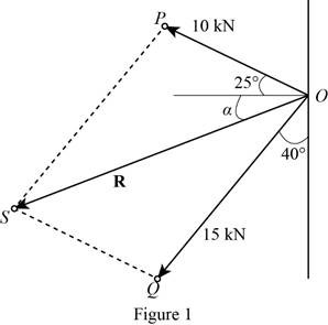
Measure the magnitude and the direction of the resultant
Therefore, the magnitude
(b)
Find the magnitude
(b)
Answer to Problem 2.3P
The magnitude
Explanation of Solution
Given information:
The tension (P) in the member B is 10 kN at an angle
The tension (Q) in the member C is 15 kN at an angle
Calculation:
Apply the triangle law for the force P and Q using the procedure as follows:
- Draw the tension force P (10 kN) using the horizontal angle
- Draw the tension force Q (15 kN) using the horizontal angle
- Draw a resultant force line by connecting the point O with the point Q. It is enclosed with triangle. The resultant force R makes an angle
- Measure the magnitude of resultant and angle
Sketch the triangle with the force P and Q as in Figure 2.
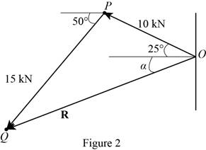
Measure the magnitude and the direction of the resultant
Therefore, the magnitude
Want to see more full solutions like this?
Chapter 2 Solutions
Vector Mechanics for Engineers: Statics, 11th Edition


 Elements Of ElectromagneticsMechanical EngineeringISBN:9780190698614Author:Sadiku, Matthew N. O.Publisher:Oxford University Press
 Mechanics of Materials (10th Edition)Mechanical EngineeringISBN:9780134319650Author:Russell C. HibbelerPublisher:PEARSON
 Thermodynamics: An Engineering ApproachMechanical EngineeringISBN:9781259822674Author:Yunus A. Cengel Dr., Michael A. BolesPublisher:McGraw-Hill Education
 Control Systems EngineeringMechanical EngineeringISBN:9781118170519Author:Norman S. NisePublisher:WILEY
 Mechanics of Materials (MindTap Course List)Mechanical EngineeringISBN:9781337093347Author:Barry J. Goodno, James M. GerePublisher:Cengage Learning
 Engineering Mechanics: StaticsMechanical EngineeringISBN:9781118807330Author:James L. Meriam, L. G. Kraige, J. N. BoltonPublisher:WILEY