
<LCPO> VECTOR MECH,STAT+DYNAMICS
12th Edition
ISBN: 9781265566296
Author: BEER
Publisher: MCG
expand_more
expand_more
format_list_bulleted
Concept explainers
Videos
Textbook Question
Chapter 2.1, Problem 2.3P
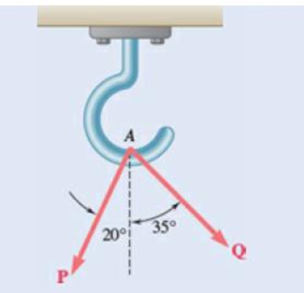
Two forces P and Q are applied as shown at point A of a hook support. Knowing that P = 75 N and Q = 125 N, determine graphically the magnitude and direction of their resultant using (a) the parallelogram law, (b) the triangle rule.
Expert Solution & Answer
Want to see the full answer?
Check out a sample textbook solution
Students have asked these similar questions
A force P of magnitude 330 lb acts on the frame
shown at point E. (a) Determine the rectangular
representation of Force Vector P. (b) Determine
the moment of P about point O. (c) Determine the
moment of P about a line joining points O and D.
7.5 in.
7.5 in.
10 in
E
A
30 in.
H
D
10 in. x
10 in.
(a) Knowing that the magnitude of the moment of force P about line CD is 100 N-m, determine the
magnitude of the force P.
(b) Express the moment of force P about line CD as a Cartesian vector.
(c) Find the magnitude of the moment of force P about point O.
600 mm
400 mm
300 mm
0
B
D
350 mm
P
3. Two forces are applied to an eye bolt fastened to a beam. Determine graphically the magnitude and
direction of their resultant using (a) the parallelogram law, Use Fig 3.
4.5 kN
25
50
6 kN
Fig 3
Chapter 2 Solutions
<LCPO> VECTOR MECH,STAT+DYNAMICS
Ch. 2.1 - Two forces are applied as shown to a hook....Ch. 2.1 - Two forces are applied as shown to a bracket...Ch. 2.1 - Two forces P and Q are applied as shown at point A...Ch. 2.1 - Two forces P and Q are applied as shown at point A...Ch. 2.1 - A stake is being pulled out of the ground by means...Ch. 2.1 - A telephone cable is clamped at A to the pole AB....Ch. 2.1 - A telephone cable is clamped at A to the pole AB....Ch. 2.1 - A disabled automobile is pulled by means of two...Ch. 2.1 - A disabled automobile is pulled by means of two...Ch. 2.1 - Two forces are applied as shown to a hook support....
Ch. 2.1 - A steel tank is to be positioned in an excavation....Ch. 2.1 - A steel tank is to be positioned in an excavation....Ch. 2.1 - A steel tank is to be positioned in an excavation....Ch. 2.1 - For the hook support of Prob. 2.10, determine by...Ch. 2.1 - The barge B is pulled by two tugboats A and C. At...Ch. 2.1 - Solve Prob. 2.1 by trigonometry.Ch. 2.1 - Solve Prob. 2.4 by trigonometry.Ch. 2.1 - For the stake of Prob. 2.5, knowing that the...Ch. 2.1 - Two structural members A and B are bolted to a...Ch. 2.1 - Two structural members A and B are bolted to a...Ch. 2.2 - Determine the x and y components of each of the...Ch. 2.2 - Determine the x and y components of each of die...Ch. 2.2 - Determine the x and y components of each of the...Ch. 2.2 - Determine the x and y components of each of the...Ch. 2.2 - Member BC exerts on member AC a force P directed...Ch. 2.2 - Member BD exerts on member ABC a force P directed...Ch. 2.2 - Prob. 2.27PCh. 2.2 - Cable AC exerts on beam AD a force P directed...Ch. 2.2 - The hydraulic cylinder BD exerts on member ABC a...Ch. 2.2 - The guy wire BD exerts on the telephone pole AC a...Ch. 2.2 - Determine the resultant of the three forces of...Ch. 2.2 - Determine the resultant of the three forces of...Ch. 2.2 - Determine the resultant of the three forces of...Ch. 2.2 - Determine the resultant of the three forces of...Ch. 2.2 - Knowing that = 35, determine the resultant of the...Ch. 2.2 - Knowing that the tension in cable BC is 725 N,...Ch. 2.2 - Knowing that = 40, determine the resultant of the...Ch. 2.2 - Knowing that = 75, determine the resultant of the...Ch. 2.2 - PROBLEM 2.39 A collar that can slide on a vertical...Ch. 2.2 - PROBLEM 2.40 For the beam of Problem 2.36,...Ch. 2.2 - PROBLEM 2.41 Determine (a) the required tension in...Ch. 2.2 - PROBLEM 2.42 For the block of Problems 2.37 and...Ch. 2.3 - Two cables are tied together at C and loaded as...Ch. 2.3 - Two forces of magnitude TA = 8 kips and TB = 15...Ch. 2.3 - The 60-lb collar A can slide on a frictionless...Ch. 2.3 - A chairlift has been stopped in the position...Ch. 2.3 - Two cables are tied together at C and are loaded...Ch. 2.3 - Two cables are tied together at C and are loaded...Ch. 2.3 - Two cables are tied together at C and loaded as...Ch. 2.3 - Two cables are tied together at C and are loaded...Ch. 2.3 - Prob. 2.47PCh. 2.3 - Knowing that = 20, determine the tension (a) in...Ch. 2.3 - Two cables are tied together at C and are loaded...Ch. 2.3 - Two cables are tied together at C and are loaded...Ch. 2.3 - Prob. 2.51PCh. 2.3 - Two forces P and Q are applied as shown to an...Ch. 2.3 - A welded connection is in equilibrium under the...Ch. 2.3 - A welded connection is in equilibrium under the...Ch. 2.3 - A sailor is being rescued using a boatswains chair...Ch. 2.3 - A sailor is being rescued using a boatswains chair...Ch. 2.3 - For the cables of Prob. 2.44, find the value of ...Ch. 2.3 - For the cables of Prob. 2.46, it is known that the...Ch. 2.3 - For the situation described in Fig. P2.48,...Ch. 2.3 - Two cables tied together at C are loaded as shown....Ch. 2.3 - A movable bin and its contents have a combined...Ch. 2.3 - Prob. 2.62PCh. 2.3 - Collar A is connected as shown to a 50-lb load and...Ch. 2.3 - Collar A is connected as shown to a 50-lb load and...Ch. 2.3 - A cable loop of length 1.5 m is placed around a...Ch. 2.3 - A 200-kg crate is to be supported by the...Ch. 2.3 - A 600-lb crate is supported by several...Ch. 2.3 - Solve parts b and d of Prob. 2.67, assuming that...Ch. 2.3 - A load Q is applied to the pulley C, which can...Ch. 2.3 - An 1800-N load Q is applied to pulley C, which can...Ch. 2.4 - Determine (a) the x, y, and z components of the...Ch. 2.4 - Determine (a) the x, y, and z components of the...Ch. 2.4 - A gun is aimed at a point A located 35 east of...Ch. 2.4 - Solve Prob. 2.73 assuming that point A is located...Ch. 2.4 - The angle between the guy wire AB and the mast is...Ch. 2.4 - The angle between the guy wire AC and the mast is...Ch. 2.4 - Cable AB is 65 ft long, and the tension in that...Ch. 2.4 - PROBLEM 2.78 Cable AC is 70 ft long, and the...Ch. 2.4 - Determine the magnitude and direction of the force...Ch. 2.4 - Determine the magnitude and direction of the force...Ch. 2.4 - Prob. 2.81PCh. 2.4 - Prob. 2.82PCh. 2.4 - Prob. 2.83PCh. 2.4 - A force acts at the origin of a coordinate system...Ch. 2.4 - Two cables BG and BH are attached to frame ACD as...Ch. 2.4 - Two cables BG and BH are attached to frame ACD as...Ch. 2.4 - In order to move a wrecked truck, two cables are...Ch. 2.4 - In order to move a wrecked truck, two cables are...Ch. 2.4 - A rectangular plate is supported by three cables...Ch. 2.4 - A rectangular plate is supported by three cables...Ch. 2.4 - Find the magnitude and direction of the resultant...Ch. 2.4 - Prob. 2.92PCh. 2.4 - Knowing that the tension is 425 lb in cable AB and...Ch. 2.4 - Knowing that the tension is 510 lb in cable AB and...Ch. 2.4 - Prob. 2.95PCh. 2.4 - Prob. 2.96PCh. 2.4 - The boom OA carries a load P and is supported by...Ch. 2.4 - Fig. P2.97 2.98 For the boom and loading of Prob....Ch. 2.5 - Three cables are used to tether a balloon as...Ch. 2.5 - A container of mass m = 120 kg is supported by...Ch. 2.5 - A 150-lb cylinder is supported by two cables AC...Ch. 2.5 - A transmission tower is held by three guy wires...Ch. 2.5 - A container is supported by three cables that are...Ch. 2.5 - A container is supported by three cables that are...Ch. 2.5 - Three cables are used to tether a balloon as...Ch. 2.5 - Three cables are used to tether a balloon as...Ch. 2.5 - A crate is supported by three cables as shown....Ch. 2.5 - A crate is supported by three cables as shown....Ch. 2.5 - A 12-lb circular plate of 7-in. radius is...Ch. 2.5 - Solve Prob. 2.105, knowing that = 45.Ch. 2.5 - Three cables are connected at A, where the forces...Ch. 2.5 - Fig. P2.107 and P2.108 2.108 Three cables are...Ch. 2.5 - Prob. 2.109PCh. 2.5 - A rectangular plate is supported by three cables...Ch. 2.5 - A transmission tower is held by three guy wires...Ch. 2.5 - A transmission tower is held by three guy wires...Ch. 2.5 - In trying to move across a slippery icy surface, a...Ch. 2.5 - Fig. P2.113 2.114 Solve Prob. 2.113 assuming that...Ch. 2.5 - For the rectangular plate of Probs. 2.109 and...Ch. 2.5 - PROBLEM 2.116 For the cable system of Problems...Ch. 2.5 - PROBLEM 2.117 For the cable system of Problems...Ch. 2.5 - Three cables are connected at D, where an upward...Ch. 2.5 - For the transmission tower of Probs. 2.111 and...Ch. 2.5 - Three wires are connected at point D, which is...Ch. 2.5 - A container of weight W is suspended from ring A,...Ch. 2.5 - Prob. 2.122PCh. 2.5 - A container of weight W is suspended from ring A....Ch. 2.5 - Prob. 2.124PCh. 2.5 - Fig. P2.113 2.114 Solve Prob. 2.113 assuming that...Ch. 2.5 - Prob. 2.126PCh. 2 - Two forces P and Q are applied to the lid of a...Ch. 2 - Determine the x and y components of each of the...Ch. 2 - A hoist trolley is subjected to the three forces...Ch. 2 - Knowing that = 55 and that boom AC exerts on pin...Ch. 2 - Two cables are tied together at C and loaded as...Ch. 2 - Two cables tied together at C are loaded as shown....Ch. 2 - The end of the coaxial cable AE is attached to the...Ch. 2 - Prob. 2.134RPCh. 2 - Find the magnitude and direction of the resultant...Ch. 2 - Cable BAC passes through a frictionless ring A and...Ch. 2 - Collars A and B are connected by a 25-in.-lang...Ch. 2 - Fig. P2.137 and P2.138 2.138 Collars A and B are...
Additional Engineering Textbook Solutions
Find more solutions based on key concepts
What is the weight in newtons of an object that has a mass of (a) 8 kg, (b) 0.04 kg, (c) 760 Mg?
Statics and Mechanics of Materials (5th Edition)
Determine the velocity of block D if end A of the rope is pulled down with a speed of vA = 3 m/s.
Engineering Mechanics: Dynamics (14th Edition)
3.3 It is known that a vertical force of 200 lb is required to remove the nail at C from the board. As the nail...
Vector Mechanics for Engineers: Statics, 11th Edition
A 20-lb force is applied to the control rod AB as shown. Knowing that the length of the rod is 9 in. and that t...
Statics and Mechanics of Materials
What is the importance of modeling in engineering? How are the mathematical models for engineering processes pr...
Heat and Mass Transfer: Fundamentals and Applications
Locate the centroid of the area. Prob. 9-17
INTERNATIONAL EDITION---Engineering Mechanics: Statics, 14th edition (SI unit)
Knowledge Booster


Learn more about
Need a deep-dive on the concept behind this application? Look no further. Learn more about this topic, mechanical-engineering and related others by exploring similar questions and additional content below.Similar questions
- Q (2): Knowing F2=420 N, F3=630 N. and the magnitude of the resultant force acting on the bracket is 650 N, directed along the positive u axis. Determine the magnitude of F and 50 its direction p.arrow_forwardCH.4 QI: A force F having a magnitude of (F) N acts along the diagonal of the parallelepiped. Determine the moment of F about the point A, using and . 250 250 mm 450mm B 650mm 250arrow_forward2) A cube of side length a is acted upon by a force F as shown. Determine the magnitude of the moment of F about the diagonal AB. B karrow_forward
- Problem 6 A force system is shown below. 50 N 90 N 40° 40 N-m 0.40 m 0.80 m 100 N a. Determine the magnitude of the resultant? b. Determine the angle that the resultant force makes with the x-axis? c. Determine the magnitude of the resultant moment acting at point 0? () 0.30 m 0.50 m ********* ******.*..arrow_forward80 mm 240 mm 80 mm 240 mm D 300 mm A rectangular plate is supported by brackets at A and B and by a wire CD. If the tension in the wire is 200 N, determine the moment along an axis from A to B of the force exerted by the wire on point C.arrow_forward-G 80° F -F 80° Two couples act on a rectangle with a base of 4m and a height of 6 m. Determine the magnitude and direction of the resultant moment, knowing that F = 85 N and G = 55 N. The resultant moment has a magnitude of direction. in thearrow_forward
- Force F = 1,665 N acts from A towards B, as shown. Determine the magnitudes of the moments of force F about the following lines in N · m. (a) OC = (N · m) (b) OD = (N · m) (c) CD = (N · m) (d) BC = (N · m) (e) DE = (N · m) (f) DF = (N · m) (g) FG = (N · m)arrow_forwardPROBLEM 3.7 A 400-N furce P is applied at Point A of the bell crank shoWn. (u) Compute the moment of the force P about O by resolving it into components along line OA and in a direction perpendicular to that line. (b) Determine the magnitude and direction of the smallest force Q applied at B that has the same moment as P about O. p00 mim 120 mmarrow_forward3.68 A steel plate is acted upon by two couples as shown. Determine (a) the moment of the couple formed by the two 40-N forces, (b) the value of a if the resultant of the two couples is 8 N· m counterclockwise and d = 820 mm, (c) the perpendicular distance between the two 24-N forces if the resultant of the two couples is zero. -600 mm- 24 NE F D 40 N d 40 N 24 N Aarrow_forward
- 2.1 Two forces are applied at point B of beam AB. Determine graphi- cally the magnitude and direction of their resultant using (a) the parallelogram law, (h) the triangle rule. A B 60 3 kN 40° 2 KNarrow_forwardPROBLEM 2.1 Two forces P and Q are applied as shown at Point A of a hook support. Knowing that P = 75 N and Q=125 N, determine graphically the magnitude and direction of their resultant using (a) the parallelogram law, (b) the triangle rule. 200l 35° Parrow_forward4.5 • Forces F and F2 act at a point. The magnitude of F is 9.00 N, and its direction is 60.0° above the x-axis in the second quadrant. The magnitude of F, is 6.00 N, and its direction is 53.1° below the x-axis in the third quadrant. (a) What are the x- and y-components of the resultant force? (b) What is the magnitude of the resultant force? ng Section 4.3 Newton's Second Law 21 12:23 e to search 12°C Cloudy AG a 4 ENG 03/05/2022 DOLL insert delete home F11 end +1- prt sc F10 CE F3 F4 F5 F6 F7 F8 F9 F12 & num lock 3 %3D 8 9 R T Y P ome + IIarrow_forward
arrow_back_ios
SEE MORE QUESTIONS
arrow_forward_ios
Recommended textbooks for you
 Elements Of ElectromagneticsMechanical EngineeringISBN:9780190698614Author:Sadiku, Matthew N. O.Publisher:Oxford University Press
 Mechanics of Materials (10th Edition)Mechanical EngineeringISBN:9780134319650Author:Russell C. HibbelerPublisher:PEARSON
 Thermodynamics: An Engineering ApproachMechanical EngineeringISBN:9781259822674Author:Yunus A. Cengel Dr., Michael A. BolesPublisher:McGraw-Hill Education
 Control Systems EngineeringMechanical EngineeringISBN:9781118170519Author:Norman S. NisePublisher:WILEY
 Mechanics of Materials (MindTap Course List)Mechanical EngineeringISBN:9781337093347Author:Barry J. Goodno, James M. GerePublisher:Cengage Learning
 Engineering Mechanics: StaticsMechanical EngineeringISBN:9781118807330Author:James L. Meriam, L. G. Kraige, J. N. BoltonPublisher:WILEY
Elements Of Electromagnetics
Mechanical Engineering
ISBN:9780190698614
Author:Sadiku, Matthew N. O.
Publisher:Oxford University Press
Mechanics of Materials (10th Edition)
Mechanical Engineering
ISBN:9780134319650
Author:Russell C. Hibbeler
Publisher:PEARSON
Thermodynamics: An Engineering Approach
Mechanical Engineering
ISBN:9781259822674
Author:Yunus A. Cengel Dr., Michael A. Boles
Publisher:McGraw-Hill Education
Control Systems Engineering
Mechanical Engineering
ISBN:9781118170519
Author:Norman S. Nise
Publisher:WILEY
Mechanics of Materials (MindTap Course List)
Mechanical Engineering
ISBN:9781337093347
Author:Barry J. Goodno, James M. Gere
Publisher:Cengage Learning
Engineering Mechanics: Statics
Mechanical Engineering
ISBN:9781118807330
Author:James L. Meriam, L. G. Kraige, J. N. Bolton
Publisher:WILEY
Dynamics - Lesson 1: Introduction and Constant Acceleration Equations; Author: Jeff Hanson;https://www.youtube.com/watch?v=7aMiZ3b0Ieg;License: Standard YouTube License, CC-BY