
Concept explainers
Videos
Determine the x and y components of each of die forces shown.
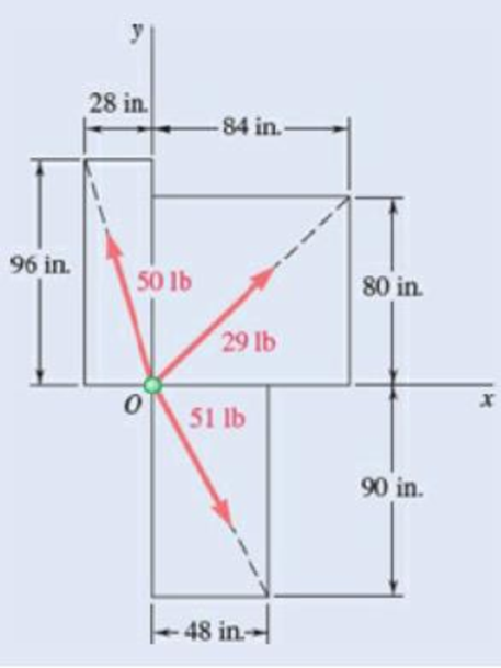
Fig. P2.22
To determine the x and y components of the forces shown in figure P2.22.
Answer to Problem 2.22P
The x component of the
The x component of the
The x component of the
Explanation of Solution
Refer figure P2.22.
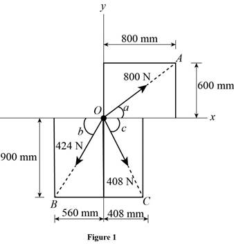
The simplified diagram of the figure P2.22 is shown in figure 1 below. Figure 1 shows all the three components of force and the corresponding position vectors and their magnitudes. Position vectors
Let
Write the equation to find the magnitude of position vector
Here,
Write the equation to find the magnitude of position vector
Here,
Write the equation to find the magnitude of position vector
Here,
Let
Write the equation to find the x component of the
Here,
Here,
Similarly write the equation to find the y component of
Here,
Rewrite the equation of y component of
Here,
Write the equation to find the x component of the
Here,
Here,
Similarly write the equation to find the y component of
Here,
Here,
Write the equation to find the x component of the
Here,
Here,
Similarly write the equation to find the y component of
Here,
Here,
Conclusion:
Substitute
Substitute
Substitute
Substitute
Substitute
Substitute
Substitute
Substitute
Substitute
Therefore, The x component of the
The x component of the
The x component of the
Want to see more full solutions like this?
Chapter 2 Solutions
<LCPO> VECTOR MECH,STAT+DYNAMICS


- D 4.8 in. C 1.84 in. B 0.8 in. 5.6 in. 2.4 in. 1.6 in. Fig. P4.43 and P4.44 4.44 A parabolic slot has been cut in plate AD, and the plate has been placed so that the slot fits two fixed, frictionless pins B and C. The equation of the slot is y = x²/4, where x and y are expressed in inches. Knowing that the maximum allowable force exerted on the roller at D is 2 lb, determine (a) the corresponding magnitude of the input force P, (b) the force each pin exerts on the plate.arrow_forward4. As for the relationship between normal stress and shear stress, it is correct that () (A) The normal stress and shear stress on the same section are perpendicular to each other; (B) The normal stress and shear stress on different sections are perpendicular to each other; (C) The normal stress and shear stress on the same section are parallel to each other; (D) The normal stress and shear stress on different sections are parallel to each other;arrow_forward2.12 Show that, for the block kept from sliding down the inclined plane by friction alone, that the line of action of the resultant of the normal force (per unit area) distributed over the base of the block must pass through the intersection of the line of action of the weight vector and the line of action of the friction force. What happens when the line of action of the weight falls to the right of point B? W Barrow_forward
- 2.2 (A). If the maximum stress allowed in the copper of the cabie of problem 2.1 is 60 MN/m2, determine the maximum tension which the cable can support. [3.75 kN.)arrow_forward2.43 A steel tube (E = 29 x 106 psi) with a 14-in. outer diameter and a -in. thickness is placed in a vise that is adjusted so that its jaws just touch the ends of the tube without exerting any pressure on them. The two forces shown are then applied to the tube. After these forces are applied, the vise is adjusted to decrease the distance between its jaws by 0.008 in. Determine (a) the forces exerted by the vise on the tube at A and D, (b) the change in length of the portion BC of the tube. Fig. P2.43 -3 in.3 in.3 in. - 3- D 8 kips B 6 kipsarrow_forwardExample 2.5. A system of forces acting on a body resting on an inclined plane is as shown in Fig. 2.15. Determine the resultant force if 0 = 60° and if W = 1000 N; N = 500 N; F = 100 N; and T = 1200 N. Horizontal Fig. 2.15arrow_forward
- 4.11 (A/B). Two bars, one of steel, the other of aluminium alloy, are each of 75 mm width and are rigidly joined together to form a rectangular bar 75 mm wide and of depth (t, +tah where t,= thickness of steel bar and = thickness of alloy bar. Determine the ratio of t, to t, in order that the neutral axis of the compound bar is coincident with the junction of the two bars. (E, - 210 GN/m; E,- 70 GN/m?.) If such a beam is 50 mm deep determine the maximum bending moment the beam can withstand if the maximum stresses in the steel and alloy are limited to 135 MN/m' and 37 MN/m respectively. [0.577; 1.47 kN m.]arrow_forwardActivity 3. From a bar subjected by an axial force P, Draw the components of P acting on the inclined plane. 30° SHAD NAO FAS VINarrow_forwardP1. Answer #6arrow_forward
- 90 mm 90 mm E -120 mm- 250 N 250 N +X B 900 N D PROBLEM 3.87 The shearing forces exerted on the cross section of a steel channel can be represented by a 900-N vertical force and two 250-N horizontal forces as shown. Replace this force and couple with a single force F applied at Point C, and determine the distance x from C to line BD. (Point C is defined as the shear center of the section.)arrow_forward2.23 The rigid bars AB and CD are supported by pins at A and D. The vertical rods are made of aluminum and bronze. Determine the vertical displacement of the point where the force P = 10 kips is applied. Neglect the weights of the members. %3Darrow_forwardMechanics of Deformable Bodies. Eight steel cables (with equal distance to each other) are supporting a circular heavy moulding of diameter 3m from an overhead point. If the moulding weighs 5 kN/m and the attachment point is 4m above it, determine the following: a. Calculate the tension of the cable. b. Determine the diameter of the wire if the allowable stress is 125 MPa. c. If the diameter of the cable is 10 mm, find the deflection of the steel cable. d. If the diameter of the cable is 10 mm, find the vertical displacement of the molder.arrow_forward
 Elements Of ElectromagneticsMechanical EngineeringISBN:9780190698614Author:Sadiku, Matthew N. O.Publisher:Oxford University Press
 Mechanics of Materials (10th Edition)Mechanical EngineeringISBN:9780134319650Author:Russell C. HibbelerPublisher:PEARSON
 Thermodynamics: An Engineering ApproachMechanical EngineeringISBN:9781259822674Author:Yunus A. Cengel Dr., Michael A. BolesPublisher:McGraw-Hill Education
 Control Systems EngineeringMechanical EngineeringISBN:9781118170519Author:Norman S. NisePublisher:WILEY
 Mechanics of Materials (MindTap Course List)Mechanical EngineeringISBN:9781337093347Author:Barry J. Goodno, James M. GerePublisher:Cengage Learning
 Engineering Mechanics: StaticsMechanical EngineeringISBN:9781118807330Author:James L. Meriam, L. G. Kraige, J. N. BoltonPublisher:WILEY