Videos
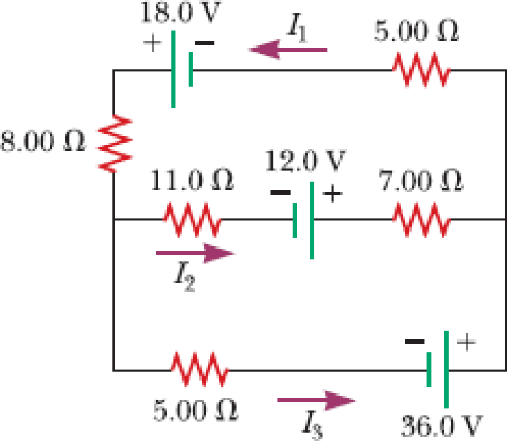
For the circuit shown in Figure P21.50, we wish to find the currents I1, I2, and I3. Use Kirchhoff’s rules to obtain equations for (a) the upper loop, (b) the lower loop, and (c) the junction on the left side. In each case, suppress units for clarity and simplify, combining the terms. (d) Solve the junction equation for I3. (e) Using the equation found in part (d), eliminate I3 from the equation found in part (b). (f) Solve the equations found in parts (a) and (e) simultaneously for the two unknowns I1 and I2. (g) Substitute the answers found in part (f) into the junction equation found in part (d), solving for I3. (h) What is the significance of the negative answer for I2?
Figure P21.50
(a)
The equations for the upper loop in the circuit diagram.
Answer to Problem 50P
The equation for the upper loop is
Explanation of Solution
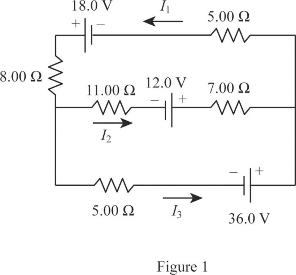
Write the expression for the Kirchhoff’s loop rule for the upper loop going counter clockwise.
Conclusion:
Therefore, the equation for the upper loop is
(b)
The equations for the lower loop in the circuit diagram.
Answer to Problem 50P
The equation for the lower loop is
Explanation of Solution
Write the expression for the Kirchhoff’s loop rule for the lower loop going counter clockwise.
Conclusion:
Therefore, the equation for the lower loop is
(c)
The equation of the junction on the left side in the circuit diagram.
Answer to Problem 50P
The equation of the junction in the left side is
Explanation of Solution
Write the expression for the Kirchhoff’s junction rule for the junction on the left side in the circuit.
Conclusion:
Therefore, the equation of the junction in the left side is
(d)
The equation for
Answer to Problem 50P
The equation for
Explanation of Solution
Use equation (III) to solve for
Conclusion:
Therefore, the equation for
(e)
The equation of the lower loop without using
Answer to Problem 50P
The equation of the lower loop without using
Explanation of Solution
Use equation (IV) in (II) to solve for the lower without using
Conclusion:
Therefore, the equation of the lower loop without using
(f)
The value of current
Answer to Problem 50P
The value of current
Explanation of Solution
Use equation (V) to solve for
Use equation (VI) in (I) to solve for
Use equation (VII) in (I) to solve for
Conclusion:
Therefore, the value of current
(g)
The value of current
Answer to Problem 50P
The value of current
Explanation of Solution
Use equation (VIII) and (VII) in (IV) to solve for
Conclusion:
Therefore, the value of current
(h)
The significance of negative sign in the current
Answer to Problem 50P
The negative sign for
Explanation of Solution
The negative sign in the value of the current
Conclusion:
Therefore, the negative sign for
Want to see more full solutions like this?
Chapter 21 Solutions
Principles of Physics


- Figure P18.26 shows a voltage divider, a circuit used to obtain a desired voltage Vout from a source voltage . Determine the required value of R2 if = 5.00 V, Vout = 1.50 V and R1 = 1.00 103 (Hint: Use Kirchhoff's loop rule, substituting Vout = IR2, to find the current. Then solve Ohms law for R2. Figure P18.26arrow_forwardThe values of the components in a simple series RC circuit containing a switch (Fig. P21.53) are C = 1.00 F, R = 2.00 106 , and = 10.0 V. At the instant 10.0 s after the switch is closed, calculate (a) the charge on the capacitor, (b) the current in the resistor, (c) the rate at which energy is being stored in the capacitor, and (d) the rate at which energy is being delivered by the battery.arrow_forwardAn automobile starter motor has an equivalent resistance of 0.0500 and is supplied by a 12.0-V battery with a 0.0100- internal resistance, (a) What is thecurrent to the motor? (b) What voltage is applied to it? (c) What power is supplied to the motor? (d) Repeat these calculations for when the battery connections are corroded and add 0.0900 to the circuit. (Significant problems are caused by even small amounts of unwanted resistance in low-voltage, high-current applications.)arrow_forward
- The circuit shown in Figure P21.47 is connected for 2.00 min. (a) Determine the current in each branch of the circuit. (b) Find the energy delivered by each battery. (c) Find the energy delivered to each resistor. (d) Identify the type of energy storage transformation that occurs in the operation of the circuit. (e) Find the total amount of energy transformed into internal energy in the resistors. Figure P21.47 Problems 47 and 48.arrow_forwardElectric current I enters a node with three resistors connected in parallel (Fig. CQ18.5). Which one of the following is correct? (a) I1 = I and I2 = I3 = 0. (b) I2 I1 and I2 I3. (c) V1 V2 V3 (d) I1 I2 I3 0. Figure CQ18.5arrow_forwardWhen resistors with different resistances are connected in parallel, which of the following must be the same for each resistor? Choose all correct answers, (a) potential difference (b) current (c) power delivered (d) charge entering each resistor in a given time interval (e) none of those answersarrow_forward
- Electric current I enters a node with three resistors connected in parallel (Fig. CQ18.5). Which one of the following is correct? (a) I1 = I and I2 = I3 = 0. (b) I2 I1 and I2 I3. (c) V1 V2 V3 (d) I1 I2 I3 0. Figure CQ18.5arrow_forwardConsider the circuit shown in Figure P21.39. Find (a) the current in the 20.0- resistor and (b) the potential difference between points a and b. Figure P21.39arrow_forwardConsider a series RC circuit as in Figure P18.35 for which R = 1.00 M, C = 5.00 F, and = 30.0 V. Find (a) the time constant of the circuit and (b) the maximum charge on the capacitor after the switch is thrown closed. (c) Find the current in the resistor 10.0 s after the switch is closed. Figure P18.35 Problem 35 and 38.arrow_forward
- Draw two graphs of charge versus time on a capacitor. Draw one for charging an initially uncharged capacitor in series with a resistor, as in the circuit in Figure 21.38, starting from t = 0. Draw the other for discharging a capacitor through a resistor, as in the circuit in Figure 21.39, starting at t = 0, with an initial charge Q0. Show at least two intervals of t.arrow_forwardIn the circuit of Figure P21.51, determine (a) the current in each resistor and (b) the potential difference across the 200- resistor. Figure P21.51arrow_forwardCalculate the power delivered to each resistor in the circuit shown in Figure P21.43. Figure P21.43arrow_forward
 Principles of Physics: A Calculus-Based TextPhysicsISBN:9781133104261Author:Raymond A. Serway, John W. JewettPublisher:Cengage Learning
 College PhysicsPhysicsISBN:9781305952300Author:Raymond A. Serway, Chris VuillePublisher:Cengage Learning
 College PhysicsPhysicsISBN:9781285737027Author:Raymond A. Serway, Chris VuillePublisher:Cengage Learning
 Physics for Scientists and Engineers: Foundations...PhysicsISBN:9781133939146Author:Katz, Debora M.Publisher:Cengage Learning
 Physics for Scientists and Engineers, Technology ...PhysicsISBN:9781305116399Author:Raymond A. Serway, John W. JewettPublisher:Cengage Learning