
College Physics
1st Edition
ISBN: 9781938168000
Author: Paul Peter Urone, Roger Hinrichs
Publisher: OpenStax College
expand_more
expand_more
format_list_bulleted
Videos
Textbook Question
Chapter 21, Problem 33CQ
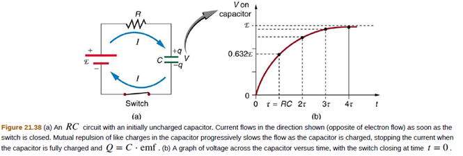
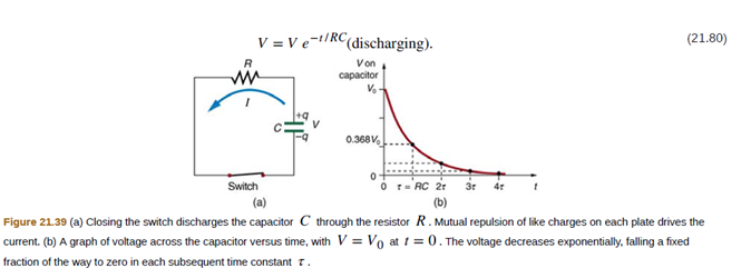
Draw two graphs of charge versus time on a capacitor. Draw one for charging an initially uncharged capacitor in series with a resistor, as in the circuit in Figure 21.38, starting from t = 0. Draw the other for discharging a capacitor through a resistor, as in the circuit in Figure 21.39, starting at t = 0, with an initial charge Q0. Show at least two intervals of t.
Expert Solution & Answer
Want to see the full answer?
Check out a sample textbook solution
Students have asked these similar questions
A 2.00-nF capacitor with an initial charge of 5.00 µC is discharged through a 2.72-kΩ resistor.
(a) Calculate the current in the resistor 9.00 µs after the resistor is connected across the terminals of the capacitor. (Let the positive direction of the current be define such that dQ/dt>0.)
(b) What charge remains on the capacitor after 8.00 µs?1.145(c) What is the (magnitude of the) maximum current in the resistor?
0.91
I already have the other two it's (a) that I keep getting wrong please help the answer has to be in this format -100 full numbers no decimal thank you.
When an initially uncharged capacitor is charged through a 25-k resistor by a 75-V dc ideal power source, it takes 0.30 ms for the capacitor to reach 50% of its maximum charge? What is the capacitance of this capacitor?
Chapter 21 Solutions
College Physics
Ch. 21 - A switch has a variable resistance that is nearly...Ch. 21 - What is the voltage across the open switch in...Ch. 21 - There is a voltage across an open switch, such as...Ch. 21 - Why is the power dissipated by a closed switch,...Ch. 21 - A student in a physics lab mistakenly wired a...Ch. 21 - Knowing that the severity of a shock depends on...Ch. 21 - Would your headlights dim when you start your...Ch. 21 - Some strings of holiday lights are wired in series...Ch. 21 - If two household lightbulbs rated 60 W and 100 W...Ch. 21 - Suppose you are doing a physics lab that asks you...
Ch. 21 - Before World War II, some radios got power through...Ch. 21 - Some light bulbs have three power settings (not...Ch. 21 - Is every emf a potential difference? Is every...Ch. 21 - Explain which battery is doing the charging and...Ch. 21 - Given a battery, an assortment of resistors, and a...Ch. 21 - Two different 12-V automobile batteries on a store...Ch. 21 - What are the advantages and disadvantages of...Ch. 21 - Semitractor trucks use four large 12-V batteries....Ch. 21 - Call all of the currents going into the junction...Ch. 21 - Apply the junction rule to junction b in Figure...Ch. 21 - (a) What is the potential difference going from...Ch. 21 - Apply the loop rule to loop afedcba in Figure...Ch. 21 - Apply the loop rule to loops abgefa and cbgedc in...Ch. 21 - Why should you not connect an ammeter directly...Ch. 21 - Suppose you are using a multimeter (one designed...Ch. 21 - Specify the points to which you could connect a...Ch. 21 - To measure currents in Figure 21.49, you would...Ch. 21 - Why can a null measurement be more accurate than...Ch. 21 - If a potentiometer is used to measure cell emfs on...Ch. 21 - Regarding the units involved in the relationship t...Ch. 21 - The RC time constant in heart defibrillation is...Ch. 21 - When making an ECG measurement, it is important to...Ch. 21 - Draw two graphs of charge versus time on a...Ch. 21 - When charging a capacitor, as discussed in...Ch. 21 - When discharging a capacitor, as discussed in...Ch. 21 - Referring to Figure 21.38, draw a graph of...Ch. 21 - A long, inexpensive extension cord is connected...Ch. 21 - In Figure 21.41. does the graph indicate the time...Ch. 21 - An electronic apparatus may have large capacitors...Ch. 21 - (a) What is the resistance often 275-O resistors...Ch. 21 - (a) What is the resistance of a 1.00 102-O, a...Ch. 21 - What are the largest and smallest resistances you...Ch. 21 - An 1800-W toaster, a 1400-W electric frying pan,...Ch. 21 - Your car’s 30.0-W headlight and 2.40-kW starter...Ch. 21 - (a) Given a48.0-V battery and 24.0-O and 96.0-O...Ch. 21 - Referring to the example combining series and...Ch. 21 - Referring to Figure 21.6: (a) Calculate P3 and...Ch. 21 - Refer to Figure 21.7 and the discussion of lights...Ch. 21 - A 240-kV power transmission line carrying...Ch. 21 - Show that if two resistors R1and R2are combined...Ch. 21 - Unreasonable Results Two resistors, one having a...Ch. 21 - Unreasonable Results Two resistors, one having a...Ch. 21 - Standard automobile batteries have six lead-acid...Ch. 21 - Car bon-zinc dry cells (sometimes referred to as...Ch. 21 - What is the output voltage of a 3.0000-V lithium...Ch. 21 - (a) What is the terminal voltage of a large 1.54-V...Ch. 21 - What is the internal resistance of an automobile...Ch. 21 - (a) Find the terminal voltage of a 12.0-V...Ch. 21 - A car battery with a 12-V emf and an internal...Ch. 21 - The hot resistance of a flashlight bulb is 2.30 ,...Ch. 21 - The label or a portable radio recommends the use...Ch. 21 - An automobile starter motor has an equivalent...Ch. 21 - A child’s electronic toy is supplied by three...Ch. 21 - (a) What is the internal resistance of a voltage...Ch. 21 - A person with body resistance between his hands of...Ch. 21 - Electric fish generate current with biological...Ch. 21 - Integrated Concepts A 12.0-V emf automobile...Ch. 21 - Unreasonable Results A 1.58-V alkaline cell with a...Ch. 21 - Unreasonable Results (a) What is the internal...Ch. 21 - Apply the loop rule to loop abcdefgha in Figure...Ch. 21 - Apply the loop rule to loop aedcba in Figure...Ch. 21 - Verify the second equation in Example 21.5 by...Ch. 21 - Verify the third equation in Example 21.5 by...Ch. 21 - Apply the junction rule at point a in Figure...Ch. 21 - Apply the loop rule to loop abcdefghija in Figure...Ch. 21 - Apply the loop rule to loop akledcba in Figure...Ch. 21 - Find the currents flowing in the circuit in Figure...Ch. 21 - Solve Example 21.5, but use loop abcdefgha instead...Ch. 21 - Find the currents flowing in the circuit in Figure...Ch. 21 - Unreasonable Results Consider the circuit in...Ch. 21 - What is the sensitivity of the galvanometer (that...Ch. 21 - What is the sensitivity of the galvanometer (that...Ch. 21 - Find the resistance that must be placed in series...Ch. 21 - Find the resistance that must be placed in series...Ch. 21 - Find the resistance that must be placed in series...Ch. 21 - Find the resistance that must be placed in...Ch. 21 - Find the resistance that must be placed in series...Ch. 21 - Find the resistance that must be placed in...Ch. 21 - Suppose you measure the terminal voltage of a...Ch. 21 - Suppose you measure the terminal voltage of a...Ch. 21 - A certain ammeter has a resistance of 5.00X10⁻⁵ ...Ch. 21 - A 1,00-?O voltmeter is placed in parallel with a...Ch. 21 - A 0.0200- ammeter is placed in series with a...Ch. 21 - Unreasonable Results Suppose you have a 40.0-...Ch. 21 - Unreasonable Results (a) What resistance would you...Ch. 21 - What is the emf x of a cell being measured in a...Ch. 21 - Calculate the emfx of a dry cell for which a...Ch. 21 - When an unknown resistance Rxis placed in a...Ch. 21 - To what value must you adjust R3to balance a...Ch. 21 - (a) What is the unknown emfx in a potentiometer...Ch. 21 - Suppose you want to measure resistances in the...Ch. 21 - The timing device in an automobile’s intermittent...Ch. 21 - A heart pacemaker fires 72 times a minute, each...Ch. 21 - The duration of a photographic flash is related to...Ch. 21 - A 2.00- and a 7.50-F capacitor can be connected in...Ch. 21 - After two time constants, what percentage of the...Ch. 21 - A 500- resistor, an uncharged 1.50-F capacitor and...Ch. 21 - A heart defibrillator being used on a patient has...Ch. 21 - An ECG monitor must have an RC time constant less...Ch. 21 - Figure 21.55 shows how a bleeder resistor is used...Ch. 21 - Using the exact exponential treatment, find how...Ch. 21 - Using the exact exponential treatment, find how...Ch. 21 - Integrated Concepts If you wish to take a picture...Ch. 21 - Integrated Concepts A flashing lamp in a Christmas...Ch. 21 - Integrated Concepts A 160F capacitor charged to...Ch. 21 - Unreasonable Results (a) Calculate the capacitance...Ch. 21 - Construct Your Own Problem Consider a camera's...Ch. 21 - Construe! Your Own Problem Consider a rechargeable...
Additional Science Textbook Solutions
Find more solutions based on key concepts
The pV-diagram of the Carnot cycle.
Sears And Zemansky's University Physics With Modern Physics
The electromagnetic spectrum of light is often arranged in terms of frequency. Which one of the following has t...
Lecture- Tutorials for Introductory Astronomy
1. If an object is not moving, does that mean that there are no forces acting on it? Explain.
College Physics: A Strategic Approach (4th Edition)
24. The 1.0 kg block in FIGURE EX7.24 is tied to the wall with a rope. It sits on top of the 2.0 kg block. The ...
Physics for Scientists and Engineers: A Strategic Approach, Vol. 1 (Chs 1-21) (4th Edition)
To increase the intensity of a wave by a factor of 50, by what factor should the amplitude be increased?
University Physics Volume 1
Check Your Understanding What is the potential on the x-axis? The z-axis?
University Physics Volume 2
Knowledge Booster


Learn more about
Need a deep-dive on the concept behind this application? Look no further. Learn more about this topic, physics and related others by exploring similar questions and additional content below.Similar questions
- Referring to Figure CQ21.4, describe what happens to the light-bulb after the switch is closed. Assume the capacitor has a large capacitance and is initially uncharged. Also assume the light illuminates when connected directly across the battery terminals.arrow_forwardConsider the circuit shown in Figure P26.24, where C1, = 6.00 F, C2 = 3.00 F. and V = 20.0 V. Capacitor C1 is first charged by closing switch S1. Switch S1 is then opened, and the charged capacitor is connected to the uncharged capacitor by closing Calculate (a) the initial charge acquired by C, and (b) the final charge on each capacitor.arrow_forwardConsider the circuit shown in Figure P20.52, where C1 = 6.00 F, C2 = 3.00 F, and V = 20.0 V. Capacitor C1 is first charged by closing switch S1. Switch S1 is then opened, and the charged capacitor is connected to the uncharged capacitor by closing S2. Calculate (a) the initial charge acquired by C1 and (b) the final charge on each capacitor. Figure P20.52arrow_forward
- Figure 21.55 shows how a bleeder resistor is used to discharge a capacitor after an electronic device is shut off allowing a person to work on the electronics with less risk of shock, (a) What is the time constant? (b) How long will it take to reduce the voltage on the capacitor to 0.250% (5% of 5%) of its full value once discharge begins? (c) If the capacitor is charged to a voltage V0through a 100-O resistance, calculate the time it takes to rise to 0.865V0(This is about two time constants.)arrow_forwardA battery is used to charge a capacitor through a resistor as shown in Figure P27.44. Show that half the energy supplied by the battery appears as internal energy in the resistor and half is stored in the capacitor. Figure P27.44arrow_forwardThe immediate cause of many deaths is ventricular fibrillation, an uncoordinated quivering of the heart, as opposed to proper beating. An electric shock to the chest can cause momentary paralysis of the heart muscle, after which the heart will sometimes start organized beating again. A defibrillator is a device that applies a strong electric shock to the chest over a time of a few milliseconds. The device contains a capacitor of a few microfarads, charged to several thousand volts. Electrodes called paddles, about 8 cm across and coated with conducting paste, are held against the chest on both sides of the heart. Their handles are insulated to prevent injury to the operator, who calls Clear! and pushes a button on one paddle to discharge the capacitor through the patient's chest Assume an energy of 3.00 102 W s is to be delivered from a 30.0-F capacitor. To what potential difference must it be charged?arrow_forward
- Figure P18.26 shows a voltage divider, a circuit used to obtain a desired voltage Vout from a source voltage . Determine the required value of R2 if = 5.00 V, Vout = 1.50 V and R1 = 1.00 103 (Hint: Use Kirchhoff's loop rule, substituting Vout = IR2, to find the current. Then solve Ohms law for R2. Figure P18.26arrow_forwardA charge Q is placed on a capacitor of capacitance C. The capacitor is connected into the circuit shown in Figure P26.37, with an open switch, a resistor, and an initially uncharged capacitor of capacitance 3C. The switch is then closed, and the circuit comes to equilibrium. In terms of Q and C, find (a) the final potential difference between the plates of each capacitor, (b) the charge on each capacitor, and (c) the final energy stored in each capacitor. (d) Find the internal energy appearing in the resistor. Figure P26.37arrow_forwardElectric current I enters a node with three resistors connected in parallel (Fig. CQ18.5). Which one of the following is correct? (a) I1 = I and I2 = I3 = 0. (b) I2 I1 and I2 I3. (c) V1 V2 V3 (d) I1 I2 I3 0. Figure CQ18.5arrow_forward
- The terminals of a battery are connected across two resistors in parallel. The resistances of the resistors are not the same. Which of the following statements is correct? Choose all that are correct. (a) The resistor with the larger resistance carries more current than the other resistor. (b) The resistor with the larger resistance carries less current than the other resistor. (c) The potential difference across each resistor is the same. (d) The potential difference across the larger resistor is greater than the potential difference across the smaller resistor. (e) The potential difference is greater across the resistor closer to the battery.arrow_forwardFigure P18.37 shows a simplified model of a cardiac defibrillator, a device used to patients in ventricular fibrillation. When the switch S is toggled to the left, the capacitor C charges through the resistor R .When the switch is toggled to the right, the capacitor discharges current through the patients torso, modeled as the resistor Rtorso, allowing the hearts normal rhythm to be reestablished. (a) If the capacitor is initially uncharged with C = 8.00 F and = 1250 V, find the value of R required to charge the capacitor to a voltage of 775 V in 1.50 s. (b) If the capacitor is then discharged across the patients torso with, Rtorso = 1250 , calculate the voltage across the capacitor after 5.00 ms. Figure P18.37arrow_forwardA heart defibrillator being used on a patient has an RC time constant of 10.0 ms due to the resistance of the patient and the capacitance of the defibrillator. (a) If the defibrillator has an 8.00F capacitance, what is the resistance of the path through the patient? (You may neglect the capacitance of the patient and the resistance of the defibrillator.) (b) If the initial voltage is 12.0 kV, how long does it take to decline to 6.00x10² V?arrow_forward
arrow_back_ios
arrow_forward_ios
Recommended textbooks for you
 College PhysicsPhysicsISBN:9781938168000Author:Paul Peter Urone, Roger HinrichsPublisher:OpenStax College
 Physics for Scientists and Engineers with Modern ...PhysicsISBN:9781337553292Author:Raymond A. Serway, John W. JewettPublisher:Cengage Learning
 Physics for Scientists and EngineersPhysicsISBN:9781337553278Author:Raymond A. Serway, John W. JewettPublisher:Cengage Learning
 Principles of Physics: A Calculus-Based TextPhysicsISBN:9781133104261Author:Raymond A. Serway, John W. JewettPublisher:Cengage Learning
 Physics for Scientists and Engineers: Foundations...PhysicsISBN:9781133939146Author:Katz, Debora M.Publisher:Cengage Learning
 Physics for Scientists and Engineers, Technology ...PhysicsISBN:9781305116399Author:Raymond A. Serway, John W. JewettPublisher:Cengage Learning
College Physics
Physics
ISBN:9781938168000
Author:Paul Peter Urone, Roger Hinrichs
Publisher:OpenStax College
Physics for Scientists and Engineers with Modern ...
Physics
ISBN:9781337553292
Author:Raymond A. Serway, John W. Jewett
Publisher:Cengage Learning
Physics for Scientists and Engineers
Physics
ISBN:9781337553278
Author:Raymond A. Serway, John W. Jewett
Publisher:Cengage Learning
Principles of Physics: A Calculus-Based Text
Physics
ISBN:9781133104261
Author:Raymond A. Serway, John W. Jewett
Publisher:Cengage Learning
Physics for Scientists and Engineers: Foundations...
Physics
ISBN:9781133939146
Author:Katz, Debora M.
Publisher:Cengage Learning
Physics for Scientists and Engineers, Technology ...
Physics
ISBN:9781305116399
Author:Raymond A. Serway, John W. Jewett
Publisher:Cengage Learning
DC Series circuits explained - The basics working principle; Author: The Engineering Mindset;https://www.youtube.com/watch?v=VV6tZ3Aqfuc;License: Standard YouTube License, CC-BY