Physics (5th Edition)
5th Edition
ISBN: 9780321976444
Author: James S. Walker
Publisher: PEARSON
expand_more
expand_more
format_list_bulleted
Videos
Textbook Question
Chapter 21, Problem 86GP
CE Predict/Explain (a) When the switch is closed in the circuit shown in Figure 21-57, does the total power dissipated in the circuit increase, decrease, or stay the same? (b) Choose the best explanation from among the following:
- I. Closing the switch adds one more resistor to the circuit. This makes it harder for the battery to supply current, which decreases the power dissipated.
- II. The equivalent resistance of the circuit is reduced by closing the switch, but the voltage remains the same. Therefore, from P = V2/R we see that the power dissipated increases.
- III. The power dissipated remains the same because power, P = IV, is independent of resistance.
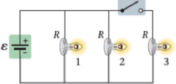
Figure 21-57
Problems 85 and 86
Expert Solution & Answer
Want to see the full answer?
Check out a sample textbook solution
Chapter 21 Solutions
Physics (5th Edition)
Ch. 21.1 - Enhance Your Understanding 1. The following...Ch. 21.2 - Enhance Your Understanding 2. If the voltage and...Ch. 21.3 - Enhance Your Understanding 3. In the following...Ch. 21.4 - The two circuits shown in Figure 21-17 have...Ch. 21.5 - Prob. 5EYUCh. 21.6 - Do two capacitors give a larger equivalent...Ch. 21.7 - Give a symbolic expression for the current that...Ch. 21 - Your body is composed of electric charges. Does it...Ch. 21 - Suppose you charge a comb by rubbing it through...Ch. 21 - An electron moving through a wire has an average...
Ch. 21 - Are car headlights connected in series or...Ch. 21 - Is it possible to connect a group of resistors of...Ch. 21 - What physical quantity do resistors connected in...Ch. 21 - What physical quantity do resistors connected in...Ch. 21 - Explain how electrical devices can begin operating...Ch. 21 - Explain the difference between resistivity and...Ch. 21 - Explain why birds can roost on high-voltage wires...Ch. 21 - Consider the circuit shown in Figure 21-36, in...Ch. 21 - A flashlight bulb carries a current of 0.38 A for...Ch. 21 - Predict/Calculate A car battery does 360 J of work...Ch. 21 - Highly sensitive ammeters can measure currents as...Ch. 21 - A television set connected to a 120-V outlet...Ch. 21 - BIO Pacemaker Batteries Pacemakers designed for...Ch. 21 - A conducting wire is quadrupled in length and...Ch. 21 - Figure 21-37 shows a plot of current versus...Ch. 21 - Predict/Explain Current-versus-voltage plots for...Ch. 21 - Prob. 9PCECh. 21 - When a potential difference of 12 V is applied to...Ch. 21 - Prob. 11PCECh. 21 - Prob. 12PCECh. 21 - Transcranial Direct-Current Stimulation In a tDCS...Ch. 21 - The four conducting cylinders shown in Figure...Ch. 21 - Predict/Calculate A bird lands on a bare copper...Ch. 21 - Prob. 16PCECh. 21 - Predict/Calculate BIO Current Through a Cell...Ch. 21 - Prob. 18PCECh. 21 - Prob. 19PCECh. 21 - BIO Resistance and Current in the Human Finger The...Ch. 21 - If a potential difference V is maintained between...Ch. 21 - Light A has four times the power rating of light B...Ch. 21 - Two lightbulbs operate on the same potential...Ch. 21 - Problems and Conceptual Exercises Section 21-3...Ch. 21 - A 65-V generator supplies 4.8 kW of power. How...Ch. 21 - A portable CD player operates with a current of 18...Ch. 21 - Find the power dissipated in a 22- electric heater...Ch. 21 - The current in a 120-V reading lamp is 2.6 A. If...Ch. 21 - Circuit A in a house has a voltage of 208 V and is...Ch. 21 - Predict/Calculate A 65-W lightbulb operates on a...Ch. 21 - Rating Car Batteries Car batteries are rated by...Ch. 21 - Predict/Explain A dozen identical lightbulbs are...Ch. 21 - A circuit consists of three resistors, R1 R2 R3,...Ch. 21 - Predict/Explain Two resistors are connected in...Ch. 21 - What is the minimum number of 88- resistors that...Ch. 21 - Find the equivalent resistance between points A...Ch. 21 - A 9.00-V battery is connected across the terminals...Ch. 21 - Holiday Lights In a string of holiday lights, 50...Ch. 21 - Your toaster has a power cord with a resistance of...Ch. 21 - Prob. 40PCECh. 21 - Predict/Calculate Three resistors, 11, 53 , and R,...Ch. 21 - A circuit consists of a battery connected to three...Ch. 21 - Predict/Calculate Three resistors, 22 , 67 , and...Ch. 21 - Prob. 44PCECh. 21 - The equivalent resistance between points A and B...Ch. 21 - Find the equivalent resistance between points A...Ch. 21 - How many 23-W lightbulbs can be connected in...Ch. 21 - The circuit in Figure 21-43 includes a battery...Ch. 21 - Predict/Calculate A 12-V battery is connected to...Ch. 21 - Predict/Calculate The terminals A and B in Figure...Ch. 21 - Predict/Calculate Suppose the battery in Figure...Ch. 21 - Predict/Calculate The current flowing through the...Ch. 21 - Predict/Calculate Four identical resistors are...Ch. 21 - Find the magnitude and direction (clockwise or...Ch. 21 - Predict/Calculate Suppose the polarity of the...Ch. 21 - Predict/Calculate It is given that point A in...Ch. 21 - Consider the circuit shown in Figure 21-47. Find...Ch. 21 - Suppose point A is grounded (V = 0) in Figure...Ch. 21 - Predict/Calculate (a) Find the current in each...Ch. 21 - Two batteries and three resistors are connected as...Ch. 21 - Two capacitors, C1 = C and C2 = 2C, are connected...Ch. 21 - Predict/Explain Two capacitors are connected in...Ch. 21 - Predict/Explain Two capacitors are connected in...Ch. 21 - A 252-F capacitor is connected in series with a...Ch. 21 - A 36-F capacitor is connected in parallel with an...Ch. 21 - Find the equivalent capacitance between points A...Ch. 21 - A 15-V battery is connected to three capacitors in...Ch. 21 - Three different circuits, each containing a switch...Ch. 21 - Terminals A and B in Figure 21-50 are connected to...Ch. 21 - Predict/Calculate You would like to add a second...Ch. 21 - Two capacitors, one 7.5 F and the other 15 F, are...Ch. 21 - The equivalent capacitance of the capacitors shown...Ch. 21 - With the switch in position A, the 11.2-F...Ch. 21 - The switch on an RC circuit is closed at t = 0....Ch. 21 - The capacitor in an RC circuit (R = 120 , C = 45...Ch. 21 - Three RC circuits have the emf, resistance, and...Ch. 21 - Consider an RC circuit with = 12.0 V, R = 195 ,...Ch. 21 - The resistor in an RC circuit has a resistance of...Ch. 21 - A flash unit for a camera has a capacitance of...Ch. 21 - Figure 21-54 shows a simplified circuit for a...Ch. 21 - Nerve Impulse Propagation The speed with which...Ch. 21 - Predict/Calculate Consider the RC circuit shown in...Ch. 21 - CE Consider the circuit shown in Figure 21-56, in...Ch. 21 - CE Predict/Explain (a) Referring to Problem 83 and...Ch. 21 - CE Consider the circuit shown in Figure 21-57, in...Ch. 21 - CE Predict/Explain (a) When the switch is closed...Ch. 21 - Suppose that points A and B in Figure 21-41 are...Ch. 21 - CE The circuit shown in Figure 21-58 shows a...Ch. 21 - CE The three circuits shown in Figure 21-59 have...Ch. 21 - Electrical Safety Codes For safety reasons,...Ch. 21 - A portable CD player uses a current of 7.5 mA at a...Ch. 21 - An electrical heating coil is immersed in 6.6 kg...Ch. 21 - Predict/Calculate Consider the circuit shown in...Ch. 21 - Prob. 94GPCh. 21 - BIO Pacemaker Pulses A pacemaker sends a pulse to...Ch. 21 - Three resistors (R,12R,2R) are connected to a...Ch. 21 - Predict/Calculate Suppose we connect a 12.0-V...Ch. 21 - National Electric Code In the United States, the...Ch. 21 - Solar Panel Power The current-versus-voltage plot...Ch. 21 - Predict/Calculate A 15.0-V battery is connected to...Ch. 21 - When two resistors, R1 and R2, are connected in...Ch. 21 - The circuit shown in Figure 21-62 is known as a...Ch. 21 - BIO Footwear Safety The American National...Ch. 21 - BIO Footwear Safety The American National...Ch. 21 - BIO Footwear Safety The American National...Ch. 21 - The standard specifies that footwear should be...Ch. 21 - Referring to Example 21-13 Suppose the three...Ch. 21 - Referring to Example 21-13 Suppose R1 = R2 = 225 ...Ch. 21 - Predict/Calculate Referring to Example 21-18...Ch. 21 - Predict/Calculate Referring to Example 21-18...
Additional Science Textbook Solutions
Find more solutions based on key concepts
The required tilting angle of the treadmill at which the weight force is equal to the missing drag force.
College Physics: A Strategic Approach (3rd Edition)
During lab, youre given a circular wire loop of resistance R and radius a with its plane perpendicular to a uni...
Essential University Physics: Volume 2 (3rd Edition)
l. Suppose you have the uniformly charged cube in FIGURE Q24.1. Can you use symmetry alone to deduce the shape ...
Physics for Scientists and Engineers: A Strategic Approach with Modern Physics (4th Edition)
What class of motion, natural or violent, did Aristotle attribute to motion of the Moon?
Conceptual Physics (12th Edition)
Write each number in decimal form.
27. 7.77 × 10⁸
Applied Physics (11th Edition)
Knowledge Booster


Learn more about
Need a deep-dive on the concept behind this application? Look no further. Learn more about this topic, physics and related others by exploring similar questions and additional content below.Similar questions
- Apply the loop rule to loops abgefa and cbgedc in Figure 21.47.arrow_forwardCheck Your Understanding When using Kirchhoff’s laws, you need to decide which loops to use and the direction of current flow through each loop. In analyzing the circuit in Example 10.7, the direction of current flow was chosen to be clockwise, from point a to point b. How would the results change if the direction of the current was chosen to be counterclockwise, from point b to point a?arrow_forwardApply the loop rule to loop aedcba in Figure 21.25.arrow_forward
- Integrated Concepts Use the ECG in Figure 20.34 to determine the heart rate in beats per minute assuming a constant time between beats. Figure 20.34 A lead II ECG with corresponding arterial blood pressure. The QRS complex is created by the depolarization and contraction of the ventricles and is followed shortly by the maximum or systolic blood pressure. See text for further description.arrow_forwardConsider the circuit in Figure 21.29 and assume the batter has no internal resistance. (i) Just after the switch is closed, what is the current in the battery? (a) 0 (b) /2R (c) 2/R (d) /R (e) impossible to determine (ii) After a very long time, what is the current in the battery? Choose from the same choices.arrow_forwardAn electronic apparatus may have large capacitors at high voltage in the power supply section, presenting a shock hazard even when the apparatus is switched off. A “bleeder resistor" is therefore placed across such a capacitor, as shown schematically in Figure 21.50, to bleed the charge from it after the apparatus is off. Why must the bleeder resistance be much greater than the effective resistance of the rest of the circuit? How does this affect the time constant for discharging the capacitor?arrow_forward
- Apply the loop rule to Loop afedcba in die preceding problem.arrow_forwardA student in a physics lab mistakenly wired a light bulb, battery, and switch as shown in Figure 21.44. Explain why the bulb is on when the switch is open, and off when the switch is closed. (Do not try this-it is hard on the battery!)arrow_forwardThe switch S in Figure 20.27 is closed at t = 0 and the current at a reference time tref 0 is Iref. If the circuit is changed as, described below and the switch is again dosed at t = 0, determine whether the current I at the same time would be greater than, less than, or equal to the original value of Iref. Indicate your answers wilt G. L. or E, respectively. (a) Both the battery voltage and the resistance R are doubled. (b) The inductance L b doubled. (c) The battery voltage . the resistance R, and the inductance L are each doubled. Figure 20.27 A series RL circuit. As the current increases toward its maximum value, the inductor produces an emf that opposes the increasing current.arrow_forward
- In view of the small currents that cause shock hazards and the larger currents that circuit breakers and fuses interrupt, how do they play a role in preventing shock hazards?arrow_forwardWhy is the power dissipated by a closed switch, such as in Figure 21.43, small?arrow_forwardAnalog meters use a galvanometer, which essentially consists of a coil of wire with a small resistance and a pointer with a scale attached. When current runs through the coil, the pointer turns; die amount the pointer turns is proportional to the amount of current running through the coil. Galvanometers can be used to make an ammeter if a resistor is placed in parallel with the galvanometer. Consider a galvanometer that has a resistance of 25.00and gives a full scale reading when a 50A current runs through it. The galvanometer is to be used to make an ammeter that has a full scale reading of 10.00 A, as shown below. Recall that an ammeter is connected in series with the circuit of interest, so all 10 A must tun through the meter, (a) What is the current through the parallel resistor in the meter? (b) What is the voltage across the parallel resistor? (c) What is the resistance of the parallel resistor?arrow_forward
arrow_back_ios
SEE MORE QUESTIONS
arrow_forward_ios
Recommended textbooks for you
 College PhysicsPhysicsISBN:9781938168000Author:Paul Peter Urone, Roger HinrichsPublisher:OpenStax College
 College PhysicsPhysicsISBN:9781305952300Author:Raymond A. Serway, Chris VuillePublisher:Cengage Learning
 College PhysicsPhysicsISBN:9781285737027Author:Raymond A. Serway, Chris VuillePublisher:Cengage Learning
 Physics for Scientists and Engineers, Technology ...PhysicsISBN:9781305116399Author:Raymond A. Serway, John W. JewettPublisher:Cengage Learning
 Principles of Physics: A Calculus-Based TextPhysicsISBN:9781133104261Author:Raymond A. Serway, John W. JewettPublisher:Cengage Learning
College Physics
Physics
ISBN:9781938168000
Author:Paul Peter Urone, Roger Hinrichs
Publisher:OpenStax College
College Physics
Physics
ISBN:9781305952300
Author:Raymond A. Serway, Chris Vuille
Publisher:Cengage Learning
College Physics
Physics
ISBN:9781285737027
Author:Raymond A. Serway, Chris Vuille
Publisher:Cengage Learning
Physics for Scientists and Engineers, Technology ...
Physics
ISBN:9781305116399
Author:Raymond A. Serway, John W. Jewett
Publisher:Cengage Learning
Principles of Physics: A Calculus-Based Text
Physics
ISBN:9781133104261
Author:Raymond A. Serway, John W. Jewett
Publisher:Cengage Learning
What is Electromagnetic Induction? | Faraday's Laws and Lenz Law | iKen | iKen Edu | iKen App; Author: Iken Edu;https://www.youtube.com/watch?v=3HyORmBip-w;License: Standard YouTube License, CC-BY