Concept explainers
Videos
CE The circuit shown in Figure 21-58 shows a resistor and two capacitors connected in series with a battery of voltage V. The circuit also has an ammeter and a switch. Initially, the switch is open and both capacitors are uncharged. The following questions refer to a time long after the switch is closed and current has ceased to flow. (a) In terms of V1 what is the voltage across the capacitor C1 ? (b) In terms of CV1 what is the charge on the right plate of C2? (c) What is the net charge that flowed through the ammeter during charging? Give your answer in terms of CV.
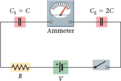
Figure 21-58
Want to see the full answer?
Check out a sample textbook solution
Chapter 21 Solutions
Physics, Books a la Carte Edition (5th Edition)
Additional Science Textbook Solutions
The Cosmic Perspective (8th Edition)
Cosmic Perspective Fundamentals
University Physics Volume 1
Conceptual Physical Science (6th Edition)
The Cosmic Perspective Fundamentals (2nd Edition)
Physics for Scientists and Engineers: A Strategic Approach, Vol. 1 (Chs 1-21) (4th Edition)


- A charge Q is placed on a capacitor of capacitance C. The capacitor is connected into the circuit shown in Figure P26.37, with an open switch, a resistor, and an initially uncharged capacitor of capacitance 3C. The switch is then closed, and the circuit comes to equilibrium. In terms of Q and C, find (a) the final potential difference between the plates of each capacitor, (b) the charge on each capacitor, and (c) the final energy stored in each capacitor. (d) Find the internal energy appearing in the resistor. Figure P26.37arrow_forwardConsider the circuit shown in Figure P26.24, where C1, = 6.00 F, C2 = 3.00 F. and V = 20.0 V. Capacitor C1 is first charged by closing switch S1. Switch S1 is then opened, and the charged capacitor is connected to the uncharged capacitor by closing Calculate (a) the initial charge acquired by C, and (b) the final charge on each capacitor.arrow_forwardThe circuit in Figure P21.59 has been connected for a long time. (a) What is the potential difference across the capacitor? (b) If the battery is disconnected from the circuit, over what time interval does the capacitor discharge to one-tenth its initial voltage?arrow_forward
- Two capacitors, C1 = 25.0 F and C2 = 5.00 F, are connected in parallel and charged with a 100-V power supply. (a) Draw a circuit diagram and (b) calculate the total energy stored in the two capacitors. (c) What If? What potential difference would be required across the same two capacitors connected in series for the combination to store the same amount of energy as in part (b)? (d) Draw a circuit diagram of the circuit described in part (c).arrow_forwardThe circuit in Figure P27.85 shows four capacitors connected to a battery. The switch S is initially open, and all capacitors have reached their final charge. The capacitances are C1 = 6.00 F, C2 = 12.00 F, C3 = 8.00 F, and C4 = 4.00 F. a. Find the potential difference across each capacitor and the charge stored in each. b. The switch is now closed. What is the new final potential difference across each capacitor and the new charge stored in each? Figure P27.85arrow_forward(a) Determine the equilibrium charge on the capacitor in the circuit of Figure P27.46 as a function of R. (b) Evaluate the charge when R = 10.0 . (c) Can the charge on the capacitor be zero? If so, for what value of R? (d) What is the maximum possible magnitude of the charge on the capacitor? For what value of R is it achieved? (c) Is it experimentally meaningful to take R = ? Explain your answer. If so, what charge magnitude does it imply? Figure P27.46arrow_forward
- Consider the circuit shown in Figure P20.52, where C1 = 6.00 F, C2 = 3.00 F, and V = 20.0 V. Capacitor C1 is first charged by closing switch S1. Switch S1 is then opened, and the charged capacitor is connected to the uncharged capacitor by closing S2. Calculate (a) the initial charge acquired by C1 and (b) the final charge on each capacitor. Figure P20.52arrow_forwardA pair of capacitors with capacitances CA = 3.70 F and CB = 6.40 F are connected in a network. What is the equivalent capacitance of the pair of capacitors if they are connected a. in parallel and b. in series?arrow_forwardThe capacitances of three capacitors are in the ratio 1:2:3. Their equivalent capacitance when all three are in parallel is 120.0 pF greater than when all three are in series. Determine the capacitance of each capacitor.arrow_forward
- For the four capacitors in the circuit shown in Figure P27.30, CA = 1.00 F, CB = 4.00 F, CC = 2.00 F, and CD = 3.00 F. What is the equivalent capacitance between points a and b? Figure P27.30arrow_forwardA Pairs of parallel wires or coaxial cables are two conductors separated by an insulator, so they have a capacitance. For a given cable, the capacitance is independent of the length if the cable is very long. A typical circuit model of a cable is shown in Figure P27.87. It is called a lumped-parameter model and represents how a unit length of the cable behaves. Find the equivalent capacitance of a. one unit length (Fig. P27.87A), b. two unit lengths (Fig. P27.87B), and c. an infinite number of unit lengths (Fig. P27.87C). Hint: For the infinite number of units, adding one more unit at the beginning does not change the equivalent capacitance.arrow_forwardThe network of capacitors shown below are all uncharged when a 300-V potential is applied between points A and B with the switch S open, (a) What is the Potential difference VE-VD? (b) What is the potential at point E after the switch is closed? (c) How much charge flows through the switch after it is closed?arrow_forward
 Physics for Scientists and Engineers: Foundations...PhysicsISBN:9781133939146Author:Katz, Debora M.Publisher:Cengage Learning
 Principles of Physics: A Calculus-Based TextPhysicsISBN:9781133104261Author:Raymond A. Serway, John W. JewettPublisher:Cengage Learning
 Physics for Scientists and Engineers, Technology ...PhysicsISBN:9781305116399Author:Raymond A. Serway, John W. JewettPublisher:Cengage Learning
 Physics for Scientists and Engineers with Modern ...PhysicsISBN:9781337553292Author:Raymond A. Serway, John W. JewettPublisher:Cengage Learning
 Physics for Scientists and EngineersPhysicsISBN:9781337553278Author:Raymond A. Serway, John W. JewettPublisher:Cengage Learning
 College PhysicsPhysicsISBN:9781938168000Author:Paul Peter Urone, Roger HinrichsPublisher:OpenStax College