
Concept explainers
Videos
Determine the x and y components of each of die forces shown.
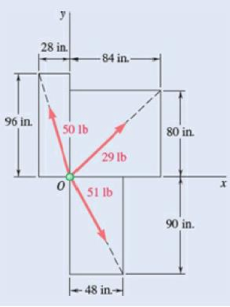
Fig. P2.22
To determine the x and y components of the forces shown in figure P2.22.
Answer to Problem 2.22P
The x component of the
The x component of the
The x component of the
Explanation of Solution
Refer figure P2.22.
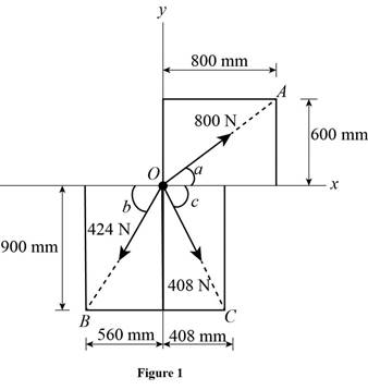
The simplified diagram of the figure P2.22 is shown in figure 1 below. Figure 1 shows all the three components of force and the corresponding position vectors and their magnitudes. Position vectors
Let
Write the equation to find the magnitude of position vector
Here,
Write the equation to find the magnitude of position vector
Here,
Write the equation to find the magnitude of position vector
Here,
Let
Write the equation to find the x component of the
Here,
Here,
Similarly write the equation to find the y component of
Here,
Rewrite the equation of y component of
Here,
Write the equation to find the x component of the
Here,
Here,
Similarly write the equation to find the y component of
Here,
Here,
Write the equation to find the x component of the
Here,
Here,
Similarly write the equation to find the y component of
Here,
Here,
Conclusion:
Substitute
Substitute
Substitute
Substitute
Substitute
Substitute
Substitute
Substitute
Substitute
Therefore, The x component of the
The x component of the
The x component of the
Want to see more full solutions like this?
Chapter 2 Solutions
VECTOR MECH...,STAT.+DYN.(LL)-W/ACCESS


- For the rectangular plate of Probs. 2.109 and 2.110, determine the tension in each of the three cables knowing that the weight of the plate is 792 N.(Reference to Problem 2.109):A rectangular plate is supported by three cables as shown. Knowing that the tension in cable AC is 60 N, determine the weight of the plate.(Reference to Problem 2.110):A rectangular plate is supported by three cables as shown. Knowing that the tension in cable AD is 520 N, determine the weight of the plate.arrow_forwardDetermine the value of w and P such that the resultant of the system is a downward force of magnitude 1200 N acting 3.6 m to the right of A. Determine the magnitude of the uniform load w. a.252 N/m b.646.1 N/m c.387.7 N/m d.553.8 N/marrow_forwardPART 2: Determine the shear force acting at each of the following locations: (a) x = 0+ ft (i.e., just to the right of support A) (b) x = 14.0 ft (i,e., at point B.) (c) x = 20.5- ft (i.e., just to the left of the support C) (d) x = 20.5+ ft (i.e., just to the right of the support (C) (e)x=27.5ft Note that x = 0 at support A. When entering your answers, use the shear-force sign convention detailed in Section 7.2. My Answers: Correct (a) V= 105.823 kips (b)V= -48.177 kips (c) V= -119.677 kips (d)V= 88 kips (e) V= 10.9998 kips PART 3: Determine the bending moment acting at each of the following locations: (a) x = 14.0- ft (i.e., just to the left of point B.) (b) x = 14.0+ ft(i.e., just to the right of point B.) (c) x = 20.5 ft (i.e. at point C) (d)x=27.5ft Note that x = 0 at support A. When entering your answers, use the shear-force sign convention detailed in Section 7.2. My Answers: Correct (a) M = 403.522 kips-ft (b) M = 193.522 kips-ft (c) M = -352.0035 kips-ft (d) M =…arrow_forward
- The length of the assembly shown decreases by 2.1 mm when an axial force is applied by means of rigud end plates. Determine the magnitude of the applied force (kN).arrow_forwardIn the following structure, determine x, such that the deformation in cable CD is two times that of deformation in cable AB. Assume, both cables are made of the same material (similar E) and have the same cross-sectional area (A).arrow_forwardA gun is aimed at a point A located 35° east of north. Knowing that the barrel of the gun forms an angle of 40° with the horizontal and that the maximum recoil force is 400 N, determine (a) the x, y, and z components of that force, (b) the values of the angles θx, θy, and θz defining the direction of the recoil force. (Assume that the x, y, and z axes are directed, respectively, east, up, and south.)arrow_forward
- A steel tank is to be positioned in an excavation. Determine by trigonometry (aa) the magnitude and direction of the smallest force P for which the resultant R of the two forces applied at A is vertical, (b) the corresponding magnitude of R.arrow_forwardA horizontal circular plate is supported by three wires at 18° angles to the vertical and attached to a support at D. Knowing that the x component of the force exerted by wire AD on the plate is 140 N, determine the magnitude of the tension in wire AD. The angle Theta is 54°.arrow_forwardA gun is aimed at a point A located 35° east of north. Knowing that the barrel of the gun forms an angle of 40° with the horizontal and that the maximum recoil force is 400 N, determine (a) the x, y, and z components of that force, (b) the values of the angles 0x, 0y, and z defining the direction of the recoil force. (Assume that the x, y, and z axes are directed, respectively, east, up, and south.)arrow_forward
- The 20 × 20-in. square plate shown weighs 56 lb and is supported by three vertical wires. Determine the weight and location of the lightest block that should be placed on the plate if the tensions in the three wires are to be equal.arrow_forwardKnowing that the tension in cable AC is 300 lb, determine the smallest angle between cable AC and the boom AB. The smallest angle is?arrow_forwardFour forces are applied at a joint of a structure. Determine the magnitude and direction of the resultant of concurrent forces.arrow_forward
 Elements Of ElectromagneticsMechanical EngineeringISBN:9780190698614Author:Sadiku, Matthew N. O.Publisher:Oxford University Press
 Mechanics of Materials (10th Edition)Mechanical EngineeringISBN:9780134319650Author:Russell C. HibbelerPublisher:PEARSON
 Thermodynamics: An Engineering ApproachMechanical EngineeringISBN:9781259822674Author:Yunus A. Cengel Dr., Michael A. BolesPublisher:McGraw-Hill Education
 Control Systems EngineeringMechanical EngineeringISBN:9781118170519Author:Norman S. NisePublisher:WILEY
 Mechanics of Materials (MindTap Course List)Mechanical EngineeringISBN:9781337093347Author:Barry J. Goodno, James M. GerePublisher:Cengage Learning
 Engineering Mechanics: StaticsMechanical EngineeringISBN:9781118807330Author:James L. Meriam, L. G. Kraige, J. N. BoltonPublisher:WILEY