
College Physics- Package
3rd Edition
ISBN: 9780133913972
Author: Knight
Publisher: PEARSON
expand_more
expand_more
format_list_bulleted
Concept explainers
Videos
Textbook Question
Chapter 23, Problem 72GP
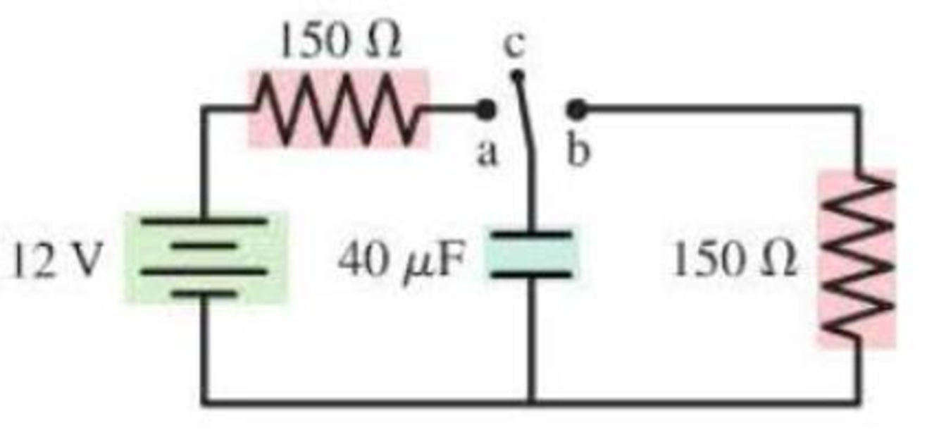
The capacitor in Figure P23.72 is initially uncharged and the switch, in position c, is not connected to either side of the circuit. The switch is now Hipped to position a for 10 ms, then to position b for 10 ms, and then brought back to position c. What is the final potential difference across the capacitor?
FIGURE P23.72
Expert Solution & Answer
Want to see the full answer?
Check out a sample textbook solution
Chapter 23 Solutions
College Physics- Package
Ch. 23 - The tip of a flashlight bulb is touching the top...Ch. 23 - A flashlight bulb is connected to a battery and is...Ch. 23 - Current Iin flows into three resistors connected...Ch. 23 - The circuit in Figure Q23.4 has two resistors,...Ch. 23 - The circuit in Figure Q23.5 has a battery and two...Ch. 23 - In the circuit shown in Figure Q23.6, bulbs A and...Ch. 23 - Figure Q23.7 shows two circuits. The two batteries...Ch. 23 - Figure Q23.8 shows two circuits. The two batteries...Ch. 23 - a. In Figure Q23.9, what fraction of current I...Ch. 23 - Two of the three resistors in Figure Q23.10 are...
Ch. 23 - Two of the three resistors in Figure Q23.11 are...Ch. 23 - Rank in order, from largest to smallest, the...Ch. 23 - The three bulbs in Figure Q23.13 are identical....Ch. 23 - The four bulbs in Figure Q23.14 are identical....Ch. 23 - Figure Q23.15 shows five identical bulbs connected...Ch. 23 - a. The three bulbs in Figure Q23.16 are identical....Ch. 23 - Initially, bulbs A and B in Figure Q23.17 are both...Ch. 23 - a. Consider the points a and b in Figure Q23.18....Ch. 23 - When the switch in Figure Q23.19 is closed, a....Ch. 23 - A voltmeter is (incorrectly) inserted into a...Ch. 23 - An ammeter is (incorrectly) inserted into a...Ch. 23 - Rank in order, from largest to smallest, the...Ch. 23 - Figure Q23.23 shows a circuit consisting of a...Ch. 23 - Figure Q23.24 shows the volt age as a function of...Ch. 23 - A charged capacitor could be connected to two...Ch. 23 - A flashing light is controlled by the charging and...Ch. 23 - A device to make an electrical measurement of skin...Ch. 23 - Consider the model of nerve conduction in...Ch. 23 - Adding a myelin sheath to an axon results in...Ch. 23 - What is the current in the circuit of Figure...Ch. 23 - Which resistor in Figure Q23.30 dissipates the...Ch. 23 - Normally, household lightbulbs are connected in...Ch. 23 - A metal wire of resistance R is cut into two...Ch. 23 - What is the value of resistor R in Figure Q23.34?...Ch. 23 - Two capacitors are connected in series. They are...Ch. 23 - If a cells membrane thickness doubles but the cell...Ch. 23 - If a cells diameter is reduced by 50% without...Ch. 23 - Draw a circuit diagram tor the circuit of Figure...Ch. 23 - Draw a circuit diagram for the circuit of Figure...Ch. 23 - Draw a circuit diagram for the circuit of Figure...Ch. 23 - In Figure P23.4, what is the current in the wire...Ch. 23 - The lightbulb in the circuit diagram of Figure...Ch. 23 - a. What are the magnitude and direction of the...Ch. 23 - a. What are the magnitude and direction of the...Ch. 23 - a. What is the potential difference across each...Ch. 23 - The current in a circuit with only one battery is...Ch. 23 - What is the equivalent resistance of each group of...Ch. 23 - What is the equivalent resistance of each group of...Ch. 23 - Prob. 12PCh. 23 - Prob. 13PCh. 23 - You have a collection of 1.0 k resistors. How can...Ch. 23 - You have a collection of six 1.0 k resistors. What...Ch. 23 - You have six 1.0 k resistors. How can you connect...Ch. 23 - What is the equivalent resistance between points a...Ch. 23 - What is the equivalent resistance between points a...Ch. 23 - The currents in two resistors in a circuit are...Ch. 23 - Two batteries supply current to the circuit in...Ch. 23 - Part of a circuit is shown in Figure P23.21. a....Ch. 23 - What is the value of resistor R in Figure P23.22?...Ch. 23 - What are the resistances R and the emf of the...Ch. 23 - The ammeter in Figure P23.24 reads 3.0 A. Find I1,...Ch. 23 - Find the current through and the potential...Ch. 23 - Find the current through and the potential...Ch. 23 - For the circuit shown in Figure P23.27, find the...Ch. 23 - Consider the potential differences between pairs...Ch. 23 - For the circuit shown in Figure P23.29, find the...Ch. 23 - A photoresistor, whose resistance decreases with...Ch. 23 - The two unknown resistors in Figure P23.31 have...Ch. 23 - A 6.0 F capacitor, a 10 F capacitor, and a 16 F...Ch. 23 - A 6.0 F capacitor, a 10 F capacitor, and a 16 F...Ch. 23 - You need a capacitance of 50 F, but you dont...Ch. 23 - You need a capacitance of 50 F, but you dont...Ch. 23 - What is the equivalent capacitance of the three...Ch. 23 - What is the equivalent capacitance of the three...Ch. 23 - For the circuit of Figure P23.38, a. What is the...Ch. 23 - For the circuit of Figure P23.39. a. What is the...Ch. 23 - What is the time constant for the discharge of the...Ch. 23 - What is the time constant for the discharge of the...Ch. 23 - After how many time constants has the voltage...Ch. 23 - A 10F capacitor initially charged to 20C is...Ch. 23 - A capacitor charging circuit consists of a...Ch. 23 - The switch in Figure P23.45 has been in position a...Ch. 23 - A 9.0-nm-thick cell membrane undergoes an action...Ch. 23 - A cell membrane has a resistance and a capacitance...Ch. 23 - Changing the thickness of the myelin sheath...Ch. 23 - A particular myelinated axon has nodes spaced 0.80...Ch. 23 - To measure signal propagation in a nerve in the...Ch. 23 - A myelinated axon conducts nerve impulses at a...Ch. 23 - How much power is dissipated by each resistor in...Ch. 23 - Two 75 W (120 V) lightbulbs are wired in series,...Ch. 23 - The corroded contacts in a lightbulb socket have...Ch. 23 - A real battery is not just an emf. We can If model...Ch. 23 - For the real battery shown in Figure P23.55,...Ch. 23 - Batteries are recharged by connecting them to a...Ch. 23 - When two resistors are connected in parallel...Ch. 23 - The 10 resistor in Figure P23.59 is dissipating 40...Ch. 23 - At this instant the current in the circuit of...Ch. 23 - What is the equivalent resistance between points a...Ch. 23 - What is the current through the battery in Figure...Ch. 23 - What is the ratio P parallel/P series of the total...Ch. 23 - You have a device that needs a voltage reference...Ch. 23 - There is a current of 0.25 A in the circuit of...Ch. 23 - A circuit youre building needs an ammeter that...Ch. 23 - A circuit youre building needs a voltmeter that...Ch. 23 - For the circuit shown in Figure P23.68, find the...Ch. 23 - You have three 12 F capacitors. Draw diagrams...Ch. 23 - Initially, the switch in Figure P23.70 is in...Ch. 23 - The capacitor in an RC circuit with a time...Ch. 23 - The capacitor in Figure P23.72 is initially...Ch. 23 - What value resistor will discharge a 1.0 F...Ch. 23 - The charging circuit for the flash system of a...Ch. 23 - A capacitor is discharged through a 100 resistor....Ch. 23 - A 50 /F capacitor that had been charged to 30 V is...Ch. 23 - The switch in Figure P23.77 has been closed for a...Ch. 23 - Intermittent windshield wipers use a variable...Ch. 23 - In Example 23.14 we estimated the capacitance of...Ch. 23 - The giant axon of a squid is 0.5 mm in diameter,...Ch. 23 - A cell has a 7.0-nm-thick membrane with a total...Ch. 23 - The Defibrillator A defibrillator is designed to...Ch. 23 - The Defibrillator A defibrillator is designed to...Ch. 23 - The Defibrillator A defibrillator is designed to...Ch. 23 - A defibrillator is designed to pass a large...Ch. 23 - The voltage produced by a single nerve or muscle...Ch. 23 - The voltage produced by a single nerve or muscle...Ch. 23 - The voltage produced by a single nerve or muscle...Ch. 23 - The voltage produced by a single nerve or muscle...
Additional Science Textbook Solutions
Find more solutions based on key concepts
3. What is free-fall, and why does it make you weightless? Briefly describe why astronauts are weightless in th...
The Cosmic Perspective
Whether the students sitting on the trunk of car to increase the traction on the icy street will help or not.
Physics (5th Edition)
55. You’re 6.0 m from one wall of the house seen in FIGURE P4.55. You want to toss a ball to your friend who i...
Physics for Scientists and Engineers: A Strategic Approach with Modern Physics (4th Edition)
Choose the best answer to etch of the following. Explain your reasoning. Which of these stars has the largest r...
Cosmic Perspective Fundamentals
8. A vertical bar moves horizontally at constant velocity through a uniform magnetic field, as shown in Figure ...
College Physics (10th Edition)
Which of the two planets (Esus or Sulis) do you think will move around the central star in the least amount of ...
Lecture- Tutorials for Introductory Astronomy
Knowledge Booster


Learn more about
Need a deep-dive on the concept behind this application? Look no further. Learn more about this topic, physics and related others by exploring similar questions and additional content below.Similar questions
- Consider the circuit shown in Figure P20.52, where C1 = 6.00 F, C2 = 3.00 F, and V = 20.0 V. Capacitor C1 is first charged by closing switch S1. Switch S1 is then opened, and the charged capacitor is connected to the uncharged capacitor by closing S2. Calculate (a) the initial charge acquired by C1 and (b) the final charge on each capacitor. Figure P20.52arrow_forwardConsider the combination of capacitors in Figure P16.42. (a) Find the equivalent single capacitance of the two capacitors in series and redraw the diagram (called diagram 1) with this equivalent capacitance. (b) In diagram 1, find the equivalent capacitance of the three capacitors in parallel and redraw the diagram as a single battery and single capacitor in a loop. (c) Compute the charge on the single equivalent capacitor. (d) Returning to diagram 1, compute the charge on each individual capacitor. Does the sum agree with the value found in part (c)? (e) What is the charge on the 24.0-F capacitor and on the 8.00-F capacitor? Compute the voltage drop across (f) the 24.0-F capacitor and (g) the 8.00-F capacitor. Figure P16.42arrow_forwardReferring to Figure CQ21.4, describe what happens to the light-bulb after the switch is closed. Assume the capacitor has a large capacitance and is initially uncharged. Also assume the light illuminates when connected directly across the battery terminals.arrow_forward
- A charge Q is placed on a capacitor of capacitance C. The capacitor is connected into the circuit shown in Figure P26.37, with an open switch, a resistor, and an initially uncharged capacitor of capacitance 3C. The switch is then closed, and the circuit comes to equilibrium. In terms of Q and C, find (a) the final potential difference between the plates of each capacitor, (b) the charge on each capacitor, and (c) the final energy stored in each capacitor. (d) Find the internal energy appearing in the resistor. Figure P26.37arrow_forwardConsider the circuit shown in Figure P26.24, where C1, = 6.00 F, C2 = 3.00 F. and V = 20.0 V. Capacitor C1 is first charged by closing switch S1. Switch S1 is then opened, and the charged capacitor is connected to the uncharged capacitor by closing Calculate (a) the initial charge acquired by C, and (b) the final charge on each capacitor.arrow_forwardThe circuit in Figure P27.85 shows four capacitors connected to a battery. The switch S is initially open, and all capacitors have reached their final charge. The capacitances are C1 = 6.00 F, C2 = 12.00 F, C3 = 8.00 F, and C4 = 4.00 F. a. Find the potential difference across each capacitor and the charge stored in each. b. The switch is now closed. What is the new final potential difference across each capacitor and the new charge stored in each? Figure P27.85arrow_forward
- A variable air capacitor used in a radio tuning circuit is made of N semicircular plates, each of radius R and positioned a distance d from its neighbors, to which it is electrically connected. As shown in Figure P20.38, a second identical set of plates is enmeshed with the first set. Each plate in the second set is halfway between two plates of the first set. The second set can rotate as a unit. Determine the capacitance as a function of the angle of rotation , where = 0 corresponds to the maximum capacitance. Figure P20.38arrow_forward(a) What is the average power output of a heart defibrillator that dissipates 400 J of energy in 10.0 ms? (b) Considering the high-power output, why doesn’t the defibrillator produce serious bums?arrow_forwardA Pairs of parallel wires or coaxial cables are two conductors separated by an insulator, so they have a capacitance. For a given cable, the capacitance is independent of the length if the cable is very long. A typical circuit model of a cable is shown in Figure P27.87. It is called a lumped-parameter model and represents how a unit length of the cable behaves. Find the equivalent capacitance of a. one unit length (Fig. P27.87A), b. two unit lengths (Fig. P27.87B), and c. an infinite number of unit lengths (Fig. P27.87C). Hint: For the infinite number of units, adding one more unit at the beginning does not change the equivalent capacitance.arrow_forward
- According to its design specification, the timer circuit delaying the closing of an elevator door is to have a capacitance of 32.0 F between two points A and B. When one circuit is being constructed, the inexpensive but durable capacitor installed between these two points is found to have capacitance 34.8 F. To meet the specification, one additional capacitor can be placed between the two points. (a) Should it be in series or in parallel with the 34.8-F capacitor? (b) What should be its capacitance? (c) What If? The next circuit comes down the assembly line with capacitance 29.8 F between A and B. To meet the specification, what additional capacitor should be installed in series or in parallel in that circuit?arrow_forwardIn Figure P27.7, capacitor 1 (C1 = 20.0 F) initially has a potential difference of 50.0 V and capacitor 2 (C2 = 5.00 F) has none. The switches are then closed simultaneously. a. Find the final charge on each capacitor after a long time has passed. b. Calculate the percentage of the initial stored energy that was lost when the switches were closed. FIGURE P27.7arrow_forwardThe capacitances of three capacitors are in the ratio 1:2:3. Their equivalent capacitance when all three are in parallel is 120.0 pF greater than when all three are in series. Determine the capacitance of each capacitor.arrow_forward
arrow_back_ios
SEE MORE QUESTIONS
arrow_forward_ios
Recommended textbooks for you
 Physics for Scientists and Engineers: Foundations...PhysicsISBN:9781133939146Author:Katz, Debora M.Publisher:Cengage Learning
 Principles of Physics: A Calculus-Based TextPhysicsISBN:9781133104261Author:Raymond A. Serway, John W. JewettPublisher:Cengage Learning
 Physics for Scientists and Engineers, Technology ...PhysicsISBN:9781305116399Author:Raymond A. Serway, John W. JewettPublisher:Cengage Learning
 Physics for Scientists and Engineers with Modern ...PhysicsISBN:9781337553292Author:Raymond A. Serway, John W. JewettPublisher:Cengage Learning
 Physics for Scientists and EngineersPhysicsISBN:9781337553278Author:Raymond A. Serway, John W. JewettPublisher:Cengage Learning
Physics for Scientists and Engineers: Foundations...
Physics
ISBN:9781133939146
Author:Katz, Debora M.
Publisher:Cengage Learning
Principles of Physics: A Calculus-Based Text
Physics
ISBN:9781133104261
Author:Raymond A. Serway, John W. Jewett
Publisher:Cengage Learning
Physics for Scientists and Engineers, Technology ...
Physics
ISBN:9781305116399
Author:Raymond A. Serway, John W. Jewett
Publisher:Cengage Learning
Physics for Scientists and Engineers with Modern ...
Physics
ISBN:9781337553292
Author:Raymond A. Serway, John W. Jewett
Publisher:Cengage Learning
Physics for Scientists and Engineers
Physics
ISBN:9781337553278
Author:Raymond A. Serway, John W. Jewett
Publisher:Cengage Learning
Electric Fields: Crash Course Physics #26; Author: CrashCourse;https://www.youtube.com/watch?v=mdulzEfQXDE;License: Standard YouTube License, CC-BY