
Videos
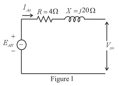
The Y-Y system in Fig. 24.53 has a balanced load and a line impedance
a. The magnitude of each phase voltage of the generator.
b. The magnitude of the line currents.
c. The total power delivered by the source.
d. The power factor angle of the entire load "seen" by the source.
e. The magnitude and angle of the current if
f The magnitude and angle of the phase voltage Van
g. The impedance of the load of each phase in rectangular coordinates.
h. The difference between the power factor of the load and the power factor of the entire system (including Zline.
i. The efficiency of the system.
Want to see the full answer?
Check out a sample textbook solution
Chapter 24 Solutions
EBK INTRODUCTORY CIRCUIT ANALYSIS


- A balanced Δ - connected load having a 15 Ω resistance in each leg is connected to a three -phase , four wires, Y-connected ABC sequence AC generator, if the line volatge EAB=, calculate 1. The phase voltages of the generator 2. The phase voltages of the load 3. The phase currents of the load 4. The line currentsarrow_forwarda) A balanced three-phase delta-connected overhead line has constants A = 0.9/10°, B = 50/64° Ω . The receiving end line voltage is held at 330kV. The line is to transmit 1000MWat a power factor of 0.9 lagging at the receiving end. Determine the following: i) Receiving end current ii) Sending end voltage b) If the line is now to transmit 900 MW at a leading power factor of 0.8 at the receiving end determine the following: i) Receiving end current ii) Sending end current PLEASE Comment on your answers to a) and b) PLEASE I NEED CORRECT SOLUTION. THANK YOU.arrow_forwardA balanced Y - connected load having a 25 Ω resistance in each leg is connected to a three -phase , four wires, Y-connected ABC sequence AC generator, if the line volatge EAB=, calculate 1. The phase voltages of the generator 2. The phase voltages of the load 3. The phase currents of the load 4. The line currentsarrow_forward
- A short 3-phase transmission line connected to a 33kV, 50 Hz generating station at the sending end is required to supply a load of 10 MW at 0·8 lagging power factor at 30 kV at the receiving end. If the minimum transmission efficiency is to be limited to 96%, estimate the per phase value of resistance and inductance of the line. [2·4 Ω; 0·028 H]arrow_forwardA three-phase generator in Y is connected to a balanced three-phase load in Δ of Z= 2.24∠26.57° Ω. If Van = 120∠30° and Vbn = 120∠150°, determine the line voltages and currents.arrow_forwardA three phase transmission line has a resistance of 10 Ω and reactance of 80 Ω per wire. The load current is 90 A and the power factor of the load is 80% lagging. The sending (generator) end voltage in the line is 44,000 V line to line. What is the receiving end voltage? a. 38.4 kV b. 34.3 kV c. 41.2 kV d. 42.3 kVarrow_forward
- 1. a) Find the reading of each wattmeter in the circuit shown if ZA=20 30° Ω, ZB=60 0° Ω, and ZC=40 −30° Ω. 2. b) Show that the sum of the wattmeter readings equals the total average power delivered to the unbalanced three-phase load.arrow_forwardIbc find the load current Vca find the line voltage Calculate the complex power on the transmission linearrow_forwardA short 3, 3 wire transmission line has an impedance per wire of 15+j20 Ω. The sending end line to line voltage is 13,200 V and the receiving end load takes 1,000 kW at a lagging power factor and the current per conductor is 70 A. What is the receiving end voltage and power factor? Note: draw the current and voltage vector diagram to facilitate your solution.arrow_forward
- 7. A single phase line is transmitting 1100 kW power to a factory at 11kV and 0.8 p.f lagging. It has a total resistance of 2 Ω and and loop reactance of 3Ω, determine (1) Voltage at sending end (2) Percentage regulation (3) Efficiency of transmission line.arrow_forwardPROBLEM 1. A three-phase transmission line is 100 km long. Its parameters are: z= (0.08 + j0.45) Ω/km y=j5 μS/km At the generating end it has a voltage of 115 kV L-L, and it is delivering a real power of PS= 51 MW and a reactive power of QS=31.6 MVARS. a. Find the parameters A,B,C and D. b. Determine the voltage and current at the receiving end. C. Calculate the regulation of the load node.arrow_forwardA balanced Y - connected load having in each leg a 10 Ω resistance in series with 10 Ω inductive reactance is connected to a three -phase , four wires, Y-connected ABC sequence AC generator, if the line volatge EAB=120 angle 0 degree space v, calculate 1. The phase voltages of the generator 2. The phase voltages of the load 3. The phase currents of the load 4. The line currentsarrow_forward
 Introductory Circuit Analysis (13th Edition)Electrical EngineeringISBN:9780133923605Author:Robert L. BoylestadPublisher:PEARSON
 Delmar's Standard Textbook Of ElectricityElectrical EngineeringISBN:9781337900348Author:Stephen L. HermanPublisher:Cengage Learning
 Programmable Logic ControllersElectrical EngineeringISBN:9780073373843Author:Frank D. PetruzellaPublisher:McGraw-Hill Education
 Fundamentals of Electric CircuitsElectrical EngineeringISBN:9780078028229Author:Charles K Alexander, Matthew SadikuPublisher:McGraw-Hill Education
 Electric Circuits. (11th Edition)Electrical EngineeringISBN:9780134746968Author:James W. Nilsson, Susan RiedelPublisher:PEARSON
 Engineering ElectromagneticsElectrical EngineeringISBN:9780078028151Author:Hayt, William H. (william Hart), Jr, BUCK, John A.Publisher:Mcgraw-hill Education,