
EBK INTRODUCTORY CIRCUIT ANALYSIS
13th Edition
ISBN: 9780100668232
Author: Boylestad
Publisher: YUZU
expand_more
expand_more
format_list_bulleted
Concept explainers
Videos
Textbook Question
Chapter 24, Problem 9P
For the Y-Y system in Fig. 24.45:
a. Find the magnitude and angle associated with the voltages EAN, EBN, and EON
b. Determine the magnitude and angle associated with each phase current of the load: lan, lbn, and Icn
c. Find the magnitude and phase angle of each line current: LAa, IBb, and lCc.
d. Determine the magnitude and phase angle of the voltage across each phase of the load:
Van, Vbn and Vcn. 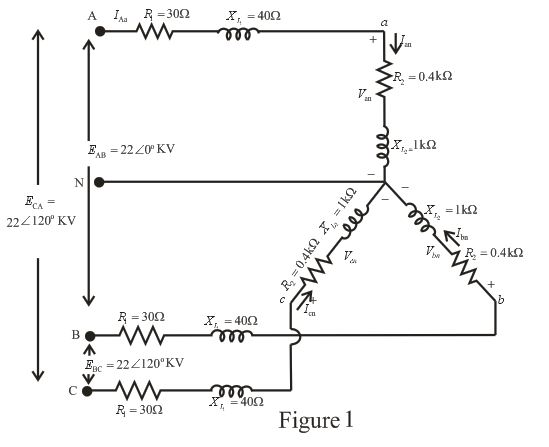
Expert Solution & Answer
Want to see the full answer?
Check out a sample textbook solution
Students have asked these similar questions
A three-phase transmission line has resistance and inductive reactance of 25V and 90V, respectively. With no load at the receiving end, a synchronous compensator there takes a current lagging by 90; the voltage is 145 kV at the sending end and 132 kV at the receiving end. Calculate the value of the current taken by the compensator.
When the load at the receiving end is 50MW, it is found that the line can operate with unchanged voltages at the sending and receiving ends, provided that the compensator takes the same current as before, but now leading by 90. Calculate the reactive power of the load
Q16
Complete the answer:
Phase sequence in a balanced three phase system is RBY, if B reaches maximum at 210°, then Y reaches maximum at ................ degree.
3. A balanced delta connected load of "17+j18 - per phase is connected at the end of a three-phase line. The line impedance is 7+j9 - per phase. The line is supplied from a three-phase source with a line-to-line voltage of 207.85 Vrms. Taking phase "a" voltage Va as reference, determine the following:
(a) Current in phase a.
(b) Total complex power supplied from the source.
(c) Magnitude of the line-to-line voltage at the load terminal.
Chapter 24 Solutions
EBK INTRODUCTORY CIRCUIT ANALYSIS
Ch. 24 - A balanced V load having a 10 resistance in each...Ch. 24 - Repeat Problem 1 if each phase impedance is...Ch. 24 - Repeat Problem 1 if each phase impedance is...Ch. 24 - The phase sequence for the Y-Y system in Fig....Ch. 24 - Repeat Problem 4 if each phase impedance are...Ch. 24 - Repeat Problem 4 if each phase impedance is...Ch. 24 - For the system in Fig. 24.43, find the magnitude...Ch. 24 - Computer the magnitude of the voltage EAB for the...Ch. 24 - For the Y-Y system in Fig. 24.45: a. Find the...Ch. 24 - For the Y-Y system of Fig. 24.46 the impedance of...
Ch. 24 - A balanced load having a 20 resistance in each...Ch. 24 - Repeat Problem 11 if each phase impedance is...Ch. 24 - Repeat Problem 11 if each phase impedance is...Ch. 24 - The phase sequence for the Y- system in Fig....Ch. 24 - Repeat Problem 14 if each phase impedance is...Ch. 24 - Repeat Problem 14 if each phase impedance are...Ch. 24 - Prob. 17PCh. 24 - For the connected load in Fig. 24.49: a. Find the...Ch. 24 - A balanced V load having a 30 resistance in each...Ch. 24 - Repeat Problem 19 if each phase impedance is...Ch. 24 - Prob. 21PCh. 24 - Prob. 22PCh. 24 - Prob. 23PCh. 24 - Repeat Problem 22 if each phase impedance is...Ch. 24 - Prob. 25PCh. 24 - Prob. 26PCh. 24 - Prob. 27PCh. 24 - The phase sequence for the - system in Fig....Ch. 24 - Repeat Problem 28 if each phase impedance is...Ch. 24 - Repeat Problem 28 if each phase impedance is...Ch. 24 - Prob. 31PCh. 24 - Prob. 32PCh. 24 - Prob. 33PCh. 24 - Find the total watts, volt-amperes reactive,...Ch. 24 - Prob. 35PCh. 24 - Find the total watts, volt-amperes reactive,...Ch. 24 - Find the total watts, volt-amperes reactive,...Ch. 24 - Prob. 38PCh. 24 - Prob. 39PCh. 24 - Find the total watts, volt-amperes reactive,...Ch. 24 - A balanced, three-phase, -connected load has a...Ch. 24 - A balanced, three-phase, Y-connected load has a...Ch. 24 - Find the total watts, volt-amperes reactive,...Ch. 24 - The Y-Y system in Fig. 24.53 has a balanced load...Ch. 24 - Prob. 45PCh. 24 - Prob. 46PCh. 24 - Repeat Problem 46 for the network in Fig. 24.47.Ch. 24 - For the three-wire system in Fig. 24.55, properly...Ch. 24 - Sketch three different ways that two wattmeters...Ch. 24 - For the Y- system in Fig. 24.56: Determine the...Ch. 24 - For the system in Fig. 24.57: Calculate the...Ch. 24 - For the three-phase, three-wire system in Fig....
Knowledge Booster


Learn more about
Need a deep-dive on the concept behind this application? Look no further. Learn more about this topic, electrical-engineering and related others by exploring similar questions and additional content below.Similar questions
- Calculate the amplitude of the line voltage per phase at the loadarrow_forwardA balanced Y-Y system with generator phase voltages Van = 15kV @ 0 degrees is connected through transmission lines to a load with phase impedance of 24+j18 Ω. What is the current phasor through the B transmission line?arrow_forwardPhase sequence in a balanced three phase system is RYB, if Y reaches maximum at 210°, then B reaches maximum atarrow_forward
- A single-phase transmission line has a resistance of 0.22 ohm and inductive reactance of 0.36 ohm. Find the voltage at the sending end to give 500kva at 2000V at the receiving end at a load power factor of 0.707 lagging. Also find the efficiency of transmission at this load.arrow_forwardA lossy transmission line of length 5 m has a characteristic impedance of (20 + j15)ohm. When the line is short circuited, the input impedance is (30+j12)ohm. i) Determine the phase constan (ii) Find the input impedance when the short circuit is replaced by a load of ZL= (40+j30)ohm.arrow_forwardA Single-Phase, 50 Hz Distribution Line has two conductors in parallel with a distance of 2.75 m apart. The radius of each conductor is 2 cm. Calculate the following: A. Inductance and Inductive Reactance of the Line per meter. B. Capacitance per meter and Capacitive Reactance in Ohm-m.arrow_forward
- A three phase transmission line is 270 km long. The series impedance of the line is (0.835+ j0.974) Ω/km and the susceptance is (j4.37x e(-6)) S/km. The voltage at the sending end is 400 kV. (a)Find the sending end current and receiving end voltage when there is no load on the line. (b)Suppose a medium transmission line and determine the maximum permissible line length if the receiving end at no-voltage is not to exceed 375 kV.arrow_forwardConsider the configuration from Problem 1, except that each phase of the transmission line has an impedance of ݆1.5 Ω. a. Determine the line currents. b. Determine the line‐neutral voltage for each branch of the 3Φ load. c. Determine the complex power consumed by the 3Φ load. d. Determine the complex power produced by the 3Φ source. e. Determine the power consumed by the transmission line. f. Determine the load power factor, and the power factor observed by the source. problem 1 : Each leg of a symmetric, Y‐connected, 3Φ load has an impedance of 10∠36.87° Ω, and is connected to A 60 Hz, balanced, positive‐sequence, Y‐connected 3Φ voltage source with Vrms .3Φ source via an ideal transmission line (that is, the connection from the source to the load has zero impedance).arrow_forwardTwo three-phase generators supply a three-phase load through separate three-phase lines. The load absorbs 30 kW at 0.8 power factor lagging. The line impedance is (1.4+j1.6) per phase between generator G1 and the load, and (0.8+j1) per phase between generator G2 and the load. If generator G1 supplies 15 kW at 0.8 poir factor lagging, with a terminal voltage of 460 V line-to-line, determine (a) the voltage at the load terminals. (b) the voltage at the terminals of generator G2, and (c) the real and reactive power supplied by generator G2. Assume balanced operation.arrow_forward
- In a balanced system, the phasor sum of the line-to-line voltages and the phasor sum of the line-to-neutral voltages are always equal to zero. (a) False (b) Truearrow_forward4) The national standard phase sequence in oman is R B Y Select one: True Falsearrow_forwardQuestion 2. The parameters of a three-phase transmission line are given as Z = (12.84+ j72.76) andy = j5.83x10 mho. At the end of the line, a power of 55 MVA with a power factor of 0.8 is drawnunder 132 kV voltage. Accordingly, calculate the line head voltage, active and reactive power values per line,and voltage regulation of the line using the nominal л circuit.arrow_forward
arrow_back_ios
SEE MORE QUESTIONS
arrow_forward_ios
Recommended textbooks for you
 Power System Analysis and Design (MindTap Course ...Electrical EngineeringISBN:9781305632134Author:J. Duncan Glover, Thomas Overbye, Mulukutla S. SarmaPublisher:Cengage Learning
Power System Analysis and Design (MindTap Course ...
Electrical Engineering
ISBN:9781305632134
Author:J. Duncan Glover, Thomas Overbye, Mulukutla S. Sarma
Publisher:Cengage Learning
How do Electric Transmission Lines Work?; Author: Practical Engineering;https://www.youtube.com/watch?v=qjY31x0m3d8;License: Standard Youtube License