
Concept explainers
Videos
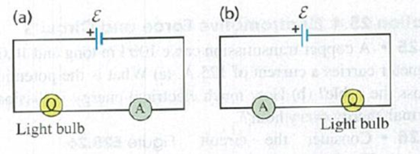
(See Discussion Question Q25.14.) An ideal ammeter A is placed in a circuit with a battery and a light bulb as shown in Fig. Q25.15a, and the ammeter reading is noted. The circuit is then reconnected as in Fig. Q25.15b, so that the positions of the ammeter and light bulb are reversed, (a) How does the ammeter reading in the situation shown in Fig. Q25.15a compare to the reading in the situation shown in Fig. Q25.15b? Explain your reasoning, (b) In which situation does the light bulb glow more brightly? Explain your reasoning.
Figure Q25.15
Want to see the full answer?
Check out a sample textbook solution
Chapter 25 Solutions
University Physics with Modern Physics (14th Edition)
Additional Science Textbook Solutions
Conceptual Integrated Science
College Physics
The Cosmic Perspective
Applied Physics (11th Edition)
Physics for Scientists and Engineers with Modern Physics
Physics: Principles with Applications


- Referring to Figure CQ21.4, describe what happens to the light-bulb after the switch is closed. Assume the capacitor has a large capacitance and is initially uncharged. Also assume the light illuminates when connected directly across the battery terminals.arrow_forwardThe temperature near the center of the Sun is thought to be 15 million degrees Celsius ( 1.5107oC ) (or kelvin). Through what voltage must a singly charged ion be accelerated to have the same energy as the average kinetic energy of ions at this temperature?arrow_forwardConsider the circuit shown in Figure P20.52, where C1 = 6.00 F, C2 = 3.00 F, and V = 20.0 V. Capacitor C1 is first charged by closing switch S1. Switch S1 is then opened, and the charged capacitor is connected to the uncharged capacitor by closing S2. Calculate (a) the initial charge acquired by C1 and (b) the final charge on each capacitor. Figure P20.52arrow_forward
- The circuit shown in Figure P28.78 is set up in the laboratory to measure an unknown capacitance C in series with a resistance R = 10.0 M powered by a battery whose emf is 6.19 V. The data given in the table are the measured voltages across the capacitor as a function of lime, where t = 0 represents the instant at which the switch is thrown to position b. (a) Construct a graph of In (/v) versus I and perform a linear least-squares fit to the data, (b) From the slope of your graph, obtain a value for the time constant of the circuit and a value for the capacitance. v(V) t(s) In (/v) 6.19 0 5.56 4.87 4.93 11.1 4.34 19.4 3.72 30.8 3.09 46.6 2.47 67.3 1.83 102.2arrow_forwardAccording to its design specification, the timer circuit delaying the closing of an elevator door is to have a capacitance of 32.0 F between two points A and B. When one circuit is being constructed, the inexpensive but durable capacitor installed between these two points is found to have capacitance 34.8 F. To meet the specification, one additional capacitor can be placed between the two points. (a) Should it be in series or in parallel with the 34.8-F capacitor? (b) What should be its capacitance? (c) What If? The next circuit comes down the assembly line with capacitance 29.8 F between A and B. To meet the specification, what additional capacitor should be installed in series or in parallel in that circuit?arrow_forwardThe immediate cause of many deaths is ventricular fibrillation, an uncoordinated quivering of the heart, as opposed to proper beating. An electric shock to the chest can cause momentary paralysis of the heart muscle, after which the heart will sometimes start organized beating again. A defibrillator is a device that applies a strong electric shock to the chest over a time of a few milliseconds. The device contains a capacitor of a few microfarads, charged to several thousand volts. Electrodes called paddles, about 8 cm across and coated with conducting paste, are held against the chest on both sides of the heart. Their handles are insulated to prevent injury to the operator, who calls Clear! and pushes a button on one paddle to discharge the capacitor through the patient's chest Assume an energy of 3.00 102 W s is to be delivered from a 30.0-F capacitor. To what potential difference must it be charged?arrow_forward
- The immediate cause of many deaths is ventricular fibrillation, an uncoordinated quivering of the heart, as opposed to proper beating. An electric shock to the chest can cause momentary paralysis of the heart muscle, after which the heart will sometimes start organized beating again. A defibrillator is a device that applies a strong electric shock to the chest over a time of a few milliseconds. The device contains a capacitor of a few microfarads, charged to several thousand volts. Electrodes called paddles, about 8 cm across and coated with conducting paste, are held against the chest on both sides of the heart. Their handles are insulated to prevent injury to the operator, who calls Clear! and pushes a button on one paddle to discharge the capacitor through the patient's chest Assume an energy of 3.00 102 W s is to be delivered from a 30.0-F capacitor. To what potential difference must it be charged?arrow_forwardA Pairs of parallel wires or coaxial cables are two conductors separated by an insulator, so they have a capacitance. For a given cable, the capacitance is independent of the length if the cable is very long. A typical circuit model of a cable is shown in Figure P27.87. It is called a lumped-parameter model and represents how a unit length of the cable behaves. Find the equivalent capacitance of a. one unit length (Fig. P27.87A), b. two unit lengths (Fig. P27.87B), and c. an infinite number of unit lengths (Fig. P27.87C). Hint: For the infinite number of units, adding one more unit at the beginning does not change the equivalent capacitance.arrow_forwardA charge Q is placed on a capacitor of capacitance C. The capacitor is connected into the circuit shown in Figure P26.37, with an open switch, a resistor, and an initially uncharged capacitor of capacitance 3C. The switch is then closed, and the circuit comes to equilibrium. In terms of Q and C, find (a) the final potential difference between the plates of each capacitor, (b) the charge on each capacitor, and (c) the final energy stored in each capacitor. (d) Find the internal energy appearing in the resistor. Figure P26.37arrow_forward
- (a) What is the average power output of a heart defibrillator that dissipates 400 J of energy in 10.0 ms? (b) Considering the high-power output, why doesn’t the defibrillator produce serious bums?arrow_forwardFigure P18.37 shows a simplified model of a cardiac defibrillator, a device used to patients in ventricular fibrillation. When the switch S is toggled to the left, the capacitor C charges through the resistor R .When the switch is toggled to the right, the capacitor discharges current through the patients torso, modeled as the resistor Rtorso, allowing the hearts normal rhythm to be reestablished. (a) If the capacitor is initially uncharged with C = 8.00 F and = 1250 V, find the value of R required to charge the capacitor to a voltage of 775 V in 1.50 s. (b) If the capacitor is then discharged across the patients torso with, Rtorso = 1250 , calculate the voltage across the capacitor after 5.00 ms. Figure P18.37arrow_forwardFigure P18.37 shows a simplified model of a cardiac defibrillator, a device used to patients in ventricular fibrillation. When the switch S is toggled to the left, the capacitor C charges through the resistor R .When the switch is toggled to the right, the capacitor discharges current through the patients torso, modeled as the resistor Rtorso, allowing the hearts normal rhythm to be reestablished. (a) If the capacitor is initially uncharged with C = 8.00 F and = 1250 V, find the value of R required to charge the capacitor to a voltage of 775 V in 1.50 s. (b) If the capacitor is then discharged across the patients torso with, Rtorso = 1250 , calculate the voltage across the capacitor after 5.00 ms. Figure P18.37arrow_forward
 Physics for Scientists and Engineers: Foundations...PhysicsISBN:9781133939146Author:Katz, Debora M.Publisher:Cengage Learning
 Principles of Physics: A Calculus-Based TextPhysicsISBN:9781133104261Author:Raymond A. Serway, John W. JewettPublisher:Cengage Learning
 College PhysicsPhysicsISBN:9781305952300Author:Raymond A. Serway, Chris VuillePublisher:Cengage Learning
 College PhysicsPhysicsISBN:9781285737027Author:Raymond A. Serway, Chris VuillePublisher:Cengage Learning
 Physics for Scientists and Engineers with Modern ...PhysicsISBN:9781337553292Author:Raymond A. Serway, John W. JewettPublisher:Cengage Learning
 Physics for Scientists and EngineersPhysicsISBN:9781337553278Author:Raymond A. Serway, John W. JewettPublisher:Cengage Learning