Videos
In the circuit shown in Fig. P25.66, R is a variable resistor whose value ranges from 0 to ∞, and a and b are the terminals of a battery that has an emf ε = 15.0 V and an internal resistance of 4.00 Ω. The ammeter and voltmeter are idealized meters. As R varies over its full range of values, what will be the largest and smallest readings of (a) the voltmeter and (b) the ammeter? (c) Sketch qualitative graphs of the readings of both meters as functions of R.
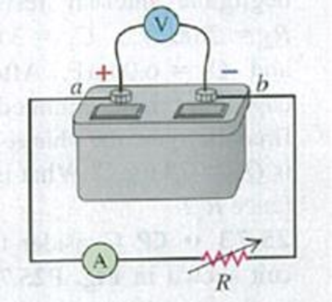
Figure P25.66
Want to see the full answer?
Check out a sample textbook solution
Chapter 25 Solutions
University Physics with Modern Physics, Books a la Carte Edition; Modified MasteringPhysics with Pearson eText -- ValuePack Access Card -- for ... eText -- Valuepack Access Card (14th Edition)
Additional Science Textbook Solutions
Life in the Universe (4th Edition)
University Physics (14th Edition)
The Cosmic Perspective Fundamentals (2nd Edition)
College Physics: A Strategic Approach (4th Edition)
Physics: Principles with Applications
Conceptual Integrated Science


- When switch S in Fig. E25.33 is open, the voltmeter V of the battery reads 3.08 V. When the switch is closed, the voltmeter reading drops to 2.97 V, and the ammeter A reads 1.65 A. Find the emf, the internal resistance of the battery, and the circuit resistance R. Assume that the two meters are ideal, so they don’t affect the circuit.arrow_forwardYou have a circuit with a battery hooked up to 2 capacitors in Parallel. The battery has a voltage of 4.3 V. The capacitors have a value of C1 = 40.0 µF and C2 = 25.0 u F. While finding the actual voltage is very helpful, it's hard to use this as a prediction because not all batteries are the same. So one way to look at this is a percentage. Even if the voltage of the battery is different, the percentage of the voltage should be the same regardless. Find the percentage of the battery voltage that is across capacitor 1. To find percentages: • Find the voltage across the specific capacitor just like previously Divide this voltage by the voltage of the battery • Multiply your answer by 100 to turn it into a percent Your answer should include: 2 Decimal Places Correct SI Units Your Answer:arrow_forwardA charged capacitor is connected to a resistor and a switch as in the figure below. The circuit has a time constant of 1.30 s. Soon after the switch is closed, the charge on the capacitor is 69.0% of its initial charge. S +Q C R (a) Find the time interval required for the capacitor to reach this charge. S (b) If R = 220 k2, what is the value of C? C = µFarrow_forward
- The emf source, ε=4.5 V, of the circuit shown in the figure has negligible internal resistance. The resistors have resistances R1=2 Ω and R2=4.7 Ω. The capacitor has a capacitance C=4.9 μF. Determine the time constant τ, in units of microseconds, for charging the capacitor. What is the charge Q on the capacitor in units of microcoulomb?arrow_forwardThe capacitor in the circuit shown below is initially uncharged. The switch is closed at t = 0 s. AVbattery = 24 V, C = 3.0 μF, and R = 2.0 Q. At sometime after the switch is closed, the voltage across the resistor is measured to be 16 V. What is the charge on the capacitor at this time, in µC? Your answer needs to have 2 significant figures, including the negative sign in your answer if needed. Do not include the positive sign if the answer is positive. No unit is needed in your answer, it is already given in the question statement.arrow_forwardthe emf source, E=3.2 V, of the circuit shown in the figure has negligible internal resistance. the resistors have resistances R1=3 ohm and R2=4.2 ohm. the capacitor has a capacitance C= 4.5uF. A) determine the time constant t , in units of microseconds for charging the capacitor. B) what is the charge Q on the capacitor in units of microcoulomb?arrow_forward
- In physics, the half-life is often used to characterize exponential decay of physical quantities such as radioactive substances. The half-life is the time required for the quantity to decay to half of its initial value. The time constant for the voltage on a capacitance discharging through a resistance is τ=RC. Find an expression for the half-life of the voltage in terms of R and C.arrow_forwardEngineering students at the University of Houston can take classes where they learn about the theory of electrical circuits. One topic they encounter in these courses is called “Ohm’s law,” and it describes the relationship between the voltage V across a resistor, the electrical current I passing through the resistor, and a quantity R known as the resistance. The law can be written as follows:V = I * R.Voltage is typically measured in volts, while current is measured in amperes (amps), and resistance is measured in ohms where 1 ohm equals 1 volt/amp. Lastly, in circuits with variable resistance, the quantities V, I, and R can depend on time.(a) Differentiate Ohm’s Law to find an equation relating the quantities V, I, R, dV/dt , dI/dt , and dR/dt .(b) Suppose that in an electrical circuit the current is increasing at a rate of 0.5 amps per second and the resistance is decreasing at a rate of 4 ohms per second. If at this same moment in time there are 3 volts of voltage and 2 ohms of…arrow_forwardAn initially uncharged capacitor of capacitance C=199μF, and a resistor with a resistance R= 6.5k2 are connected to a battery with a voltage V=20V as shown in the figure below. The switch is closed at r=0. What would be the voltage across the capacitor one time constant after the switch is closed? Express your answer in units volts using one decimal place. Yanıtınızı ekleyin. S VI R www C ...arrow_forward
- Three capacitors with capacitances C1 = C, C2 = 3C, and C3 = 5C, are in a circuit as shown. The source has potential difference ΔV = 17 V. It is observed that one plate of the capacitor C3 has a charge of q = 5 mC. Write an expression for the capacitance C (that is, the capacitance of the first capacitor), in terms of q and ΔV.arrow_forwardTwo capacitors are connected in a circuit in series. The capacitances are C1 = 18 μF, and C2 = 8.5 μF and Ctot=5.77μF. Calculate the numerical value of Q in C given ΔV = 19 V.arrow_forwardA circuit with a resistance R = 88 Ω is connected to a battery with potential difference across the terminals of ΔV = 6.5 V. a. Input an expression for the current passing through the circuit, I. (b) What is the current in milliamps, mA? (c) If the resistance of the circuit was increased by a factor of ten, Rnew = 10R, what is the new current in milliamps, mA?arrow_forward
 College PhysicsPhysicsISBN:9781305952300Author:Raymond A. Serway, Chris VuillePublisher:Cengage Learning
 University Physics (14th Edition)PhysicsISBN:9780133969290Author:Hugh D. Young, Roger A. FreedmanPublisher:PEARSON
 Introduction To Quantum MechanicsPhysicsISBN:9781107189638Author:Griffiths, David J., Schroeter, Darrell F.Publisher:Cambridge University Press
 Physics for Scientists and EngineersPhysicsISBN:9781337553278Author:Raymond A. Serway, John W. JewettPublisher:Cengage Learning
 Lecture- Tutorials for Introductory AstronomyPhysicsISBN:9780321820464Author:Edward E. Prather, Tim P. Slater, Jeff P. Adams, Gina BrissendenPublisher:Addison-Wesley
 College Physics: A Strategic Approach (4th Editio...PhysicsISBN:9780134609034Author:Randall D. Knight (Professor Emeritus), Brian Jones, Stuart FieldPublisher:PEARSON